Cube mapping

Last updated
The lower left image shows a scene with a viewpoint marked with a black dot. The upper image shows the net of the cube mapping as seen from that viewpoint, and the lower right image shows the cube superimposed on the original scene. Panorama cube map.png
The lower left image shows a scene with a viewpoint marked with a black dot. The upper image shows the net of the cube mapping as seen from that viewpoint, and the lower right image shows the cube superimposed on the original scene.

In computer graphics, cube mapping is a method of environment mapping that uses the six faces of a cube as the map shape. The environment is projected onto the sides of a cube and stored as six square textures, or unfolded into six regions of a single texture.

Contents

The cube map is generated by first rendering the scene six times from a viewpoint, with the views defined by a 90 degree view frustum representing each cube face. [1] Or if the environment is first considered to be projected onto a sphere, then each face of the cube is its gnomonic projection.

In the majority of cases, cube mapping is preferred over the older method of sphere mapping because it eliminates many of the problems that are inherent in sphere mapping such as image distortion, viewpoint dependency, and computational inefficiency. Also, cube mapping provides a much larger capacity to support real-time rendering of reflections relative to sphere mapping because the combination of inefficiency and viewpoint dependency severely limits the ability of sphere mapping to be applied when there is a consistently changing viewpoint.

Variants of cube mapping are also commonly used in 360 video projection.

History

Cube mapping was first proposed in 1986 by Ned Greene in his paper “Environment Mapping and Other Applications of World Projections”, [2] ten years after environment mapping was first put forward by Jim Blinn and Martin Newell. However, hardware limitations on the ability to access six texture images simultaneously made it infeasible to implement cube mapping without further technological developments. This problem was remedied in 1999 with the release of the Nvidia GeForce 256. Nvidia touted cube mapping in hardware as “a breakthrough image quality feature of GeForce 256 that ... will allow developers to create accurate, real-time reflections. Accelerated in hardware, cube environment mapping will free up the creativity of developers to use reflections and specular lighting effects to create interesting, immersive environments.” [3] Today, cube mapping is still used in a variety of graphical applications as a favored method of environment mapping.

Advantages

Cube mapping is preferred over other methods of environment mapping because of its relative simplicity. Also, cube mapping produces results that are similar to those obtained by ray tracing, but is much more computationally efficient – the moderate reduction in quality is compensated for by large gains in efficiency.

Predating cube mapping, sphere mapping has many inherent flaws that made it impractical for most applications. Sphere mapping is view-dependent, meaning that a different texture is necessary for each viewpoint. Therefore, in applications where the viewpoint is mobile, it would be necessary to dynamically generate a new sphere mapping for each new viewpoint (or, to pre-generate a mapping for every viewpoint). Also, a texture mapped onto a sphere's surface must be stretched and compressed, and warping and distortion (particularly along the edge of the sphere) are a direct consequence of this. Although these image flaws can be reduced using certain tricks and techniques like “pre-stretching”, this just adds another layer of complexity to sphere mapping.

Paraboloid mapping provides some improvement on the limitations of sphere mapping, however it requires two rendering passes in addition to special image warping operations and more involved computation.

Conversely, cube mapping requires only a single render pass, and due to its simple nature, is very easy for developers to comprehend and generate. Also, cube mapping uses the entire resolution of the texture image, compared to sphere and paraboloid mappings, which also allows it to use lower resolution images to achieve the same quality. Although handling the seams of the cube map is a problem, algorithms have been developed to handle seam behavior and result in a seamless reflection.

Disadvantages

If a new object or new lighting is introduced into scene or if some object that is reflected in it is moving or changing in some manner, then the reflection changes and the cube map must be re-rendered. When the cube map is affixed to an object that moves through the scene then the cube map must also be re-rendered from that new position.[ citation needed ]

Applications

Stable specular highlights

Computer-aided design (CAD) programs use specular highlights as visual cues to convey a sense of surface curvature when rendering 3D objects. However, many CAD programs exhibit problems in sampling specular highlights because the specular lighting computations are only performed at the vertices of the mesh used to represent the object, and interpolation is used to estimate lighting across the surface of the object. Problems occur when the mesh vertices are not dense enough, resulting in insufficient sampling of the specular lighting. This in turn results in highlights with brightness proportionate to the distance from mesh vertices, ultimately compromising the visual cues that indicate curvature. Unfortunately, this problem cannot be solved simply by creating a denser mesh, as this can greatly reduce the efficiency of object rendering.

Cube maps provide a fairly straightforward and efficient solution to rendering stable specular highlights. Multiple specular highlights can be encoded into a cube map texture, which can then be accessed by interpolating across the surface's reflection vector to supply coordinates. Relative to computing lighting at individual vertices, this method provides cleaner results that more accurately represent curvature. Another advantage to this method is that it scales well, as additional specular highlights can be encoded into the texture at no increase in the cost of rendering. However, this approach is limited in that the light sources must be either distant or infinite lights, although fortunately this is usually the case in CAD programs.

Skyboxes

RenderWithCubemap.png
RenderWithoutCubemap.png
Renders using cubemaps can look better in outdoor scenes. (Left is with a cubemap, right is with a basic sun light). Rendered in Blender Cycles.
Example of a texture that can be mapped to the faces of a cubic skybox, with faces labelled Skybox example.png
Example of a texture that can be mapped to the faces of a cubic skybox, with faces labelled

Perhaps the most advanced application of cube mapping is to create pre-rendered panoramic sky images which are then rendered by the graphical engine as faces of a cube at practically infinite distance with the view point located in the center of the cube. The perspective projection of the cube faces done by the graphics engine undoes the effects of projecting the environment to create the cube map, so that the observer experiences an illusion of being surrounded by the scene which was used to generate the skybox. This technique has found a widespread use in video games since it allows designers to add complex (albeit not explorable) environments to a game at almost no performance cost.

Skylight illumination

Cube maps can be useful for modelling outdoor illumination accurately. Simply modelling sunlight as a single infinite light oversimplifies outdoor illumination and results in unrealistic lighting. Although plenty of light does come from the sun, the scattering of rays in the atmosphere causes the whole sky to act as a light source (often referred to as skylight illumination). However, by using a cube map the diffuse contribution from skylight illumination can be captured. Unlike environment maps where the reflection vector is used, this method accesses the cube map based on the surface normal vector to provide a fast approximation of the diffuse illumination from the skylight. The one downside to this method is that computing cube maps to properly represent a skylight is very complex; one recent process is computing the spherical harmonic basis that best represents the low frequency diffuse illumination from the cube map. However, a considerable amount of research has been done to effectively model skylight illumination.

Dynamic reflection

Cube-mapped reflections in action Environment mapping.png
Cube-mapped reflections in action

Basic environment mapping uses a static cube map - although the object can be moved and distorted, the reflected environment stays consistent. However, a cube map texture can be consistently updated to represent a dynamically changing environment (for example, trees swaying in the wind). A simple yet costly way to generate dynamic reflections, involves building the cube maps at runtime for every frame. Although this is far less efficient than static mapping because of additional rendering steps, it can still be performed at interactive rates.

Unfortunately, this technique does not scale well when multiple reflective objects are present. A unique dynamic environment map is usually required for each reflective object. Also, further complications are added if reflective objects can reflect each other - dynamic cube maps can be recursively generated approximating the effects normally generated using raytracing.

Global illumination

An algorithm for global illumination computation at interactive rates using a cube-map data structure, was presented at ICCVG 2002.

Projection textures

Another application which found widespread use in video games is projective texture mapping. It relies on cube maps to project images of an environment onto the surrounding scene; for example, a point light source is tied to a cube map which is a panoramic image shot from inside a lantern cage or a window frame through which the light is filtering. This enables a game developer to achieve realistic lighting without having to complicate the scene geometry or resort to expensive real-time shadow volume computations.

Memory addressing

This illustration shows how a cube map is indexed and addressed. Cube map.svg
This illustration shows how a cube map is indexed and addressed.

A cube texture indexes six texture maps from 0 to 5 in order Positive X, Negative X, Positive Y, Negative Y, Positive Z, Negative Z. [4] [5] The images are stored with the origin at the lower left of the image. The Positive X and Y faces must reverse the Z coordinate and the Negative Z face must negate the X coordinate. If given the face, and texture coordinates , the non-normalized vector can be computed by the function:

voidconvert_cube_uv_to_xyz(intindex,floatu,floatv,float*x,float*y,float*z){// convert range 0 to 1 to -1 to 1floatuc=2.0f*u-1.0f;floatvc=2.0f*v-1.0f;switch(index){case0:*x=1.0f;*y=vc;*z=-uc;break;// POSITIVE Xcase1:*x=-1.0f;*y=vc;*z=uc;break;// NEGATIVE Xcase2:*x=uc;*y=1.0f;*z=-vc;break;// POSITIVE Ycase3:*x=uc;*y=-1.0f;*z=vc;break;// NEGATIVE Ycase4:*x=uc;*y=vc;*z=1.0f;break;// POSITIVE Zcase5:*x=-uc;*y=vc;*z=-1.0f;break;// NEGATIVE Z}}

Likewise, a vector can be converted to the face index and texture coordinates with the function:

voidconvert_xyz_to_cube_uv(floatx,floaty,floatz,int*index,float*u,float*v){floatabsX=fabs(x);floatabsY=fabs(y);floatabsZ=fabs(z);intisXPositive=x>0?1:0;intisYPositive=y>0?1:0;intisZPositive=z>0?1:0;floatmaxAxis,uc,vc;// POSITIVE Xif(isXPositive&&absX>=absY&&absX>=absZ){// u (0 to 1) goes from +z to -z// v (0 to 1) goes from -y to +ymaxAxis=absX;uc=-z;vc=y;*index=0;}// NEGATIVE Xif(!isXPositive&&absX>=absY&&absX>=absZ){// u (0 to 1) goes from -z to +z// v (0 to 1) goes from -y to +ymaxAxis=absX;uc=z;vc=y;*index=1;}// POSITIVE Yif(isYPositive&&absY>=absX&&absY>=absZ){// u (0 to 1) goes from -x to +x// v (0 to 1) goes from +z to -zmaxAxis=absY;uc=x;vc=-z;*index=2;}// NEGATIVE Yif(!isYPositive&&absY>=absX&&absY>=absZ){// u (0 to 1) goes from -x to +x// v (0 to 1) goes from -z to +zmaxAxis=absY;uc=x;vc=z;*index=3;}// POSITIVE Zif(isZPositive&&absZ>=absX&&absZ>=absY){// u (0 to 1) goes from -x to +x// v (0 to 1) goes from -y to +ymaxAxis=absZ;uc=x;vc=y;*index=4;}// NEGATIVE Zif(!isZPositive&&absZ>=absX&&absZ>=absY){// u (0 to 1) goes from +x to -x// v (0 to 1) goes from -y to +ymaxAxis=absZ;uc=-x;vc=y;*index=5;}// Convert range from -1 to 1 to 0 to 1*u=0.5f*(uc/maxAxis+1.0f);*v=0.5f*(vc/maxAxis+1.0f);}

Related Research Articles

<span class="mw-page-title-main">Rendering (computer graphics)</span> Process of generating an image from a model

Rendering or image synthesis is the process of generating a photorealistic or non-photorealistic image from a 2D or 3D model by means of a computer program. The resulting image is referred to as the render. Multiple models can be defined in a scene file containing objects in a strictly defined language or data structure. The scene file contains geometry, viewpoint, texture, lighting, and shading information describing the virtual scene. The data contained in the scene file is then passed to a rendering program to be processed and output to a digital image or raster graphics image file. The term "rendering" is analogous to the concept of an artist's impression of a scene. The term "rendering" is also used to describe the process of calculating effects in a video editing program to produce the final video output.

<span class="mw-page-title-main">Global illumination</span> Group of rendering algorithms used in 3D computer graphics

Global illumination (GI), or indirect illumination, is a group of algorithms used in 3D computer graphics that are meant to add more realistic lighting to 3D scenes. Such algorithms take into account not only the light that comes directly from a light source, but also subsequent cases in which light rays from the same source are reflected by other surfaces in the scene, whether reflective or not.

<span class="mw-page-title-main">Radiosity (computer graphics)</span> Computer graphics rendering method using diffuse reflection

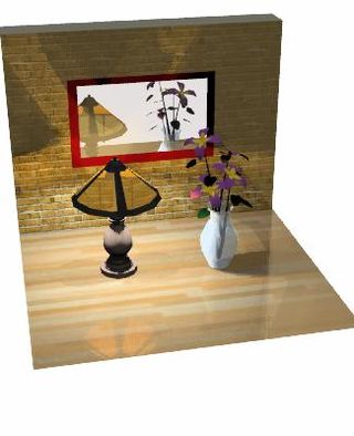
In 3D computer graphics, radiosity is an application of the finite element method to solving the rendering equation for scenes with surfaces that reflect light diffusely. Unlike rendering methods that use Monte Carlo algorithms, which handle all types of light paths, typical radiosity only account for paths which leave a light source and are reflected diffusely some number of times before hitting the eye. Radiosity is a global illumination algorithm in the sense that the illumination arriving on a surface comes not just directly from the light sources, but also from other surfaces reflecting light. Radiosity is viewpoint independent, which increases the calculations involved, but makes them useful for all viewpoints.

<span class="mw-page-title-main">Texture mapping</span> Method of defining surface detail on a computer-generated graphic or 3D model

Texture mapping is a method for mapping a texture on a computer-generated graphic. Texture here can be high frequency detail, surface texture, or color.

The Phong reflection model is an empirical model of the local illumination of points on a surface designed by the computer graphics researcher Bui Tuong Phong. In 3D computer graphics, it is sometimes referred to as "Phong shading", particularly if the model is used with the interpolation method of the same name and in the context of pixel shaders or other places where a lighting calculation can be referred to as “shading”.

<span class="mw-page-title-main">Normal mapping</span> Texture mapping technique

In 3D computer graphics, normal mapping, or Dot3 bump mapping, is a texture mapping technique used for faking the lighting of bumps and dents – an implementation of bump mapping. It is used to add details without using more polygons. A common use of this technique is to greatly enhance the appearance and details of a low polygon model by generating a normal map from a high polygon model or height map.

2.5D perspective refers to gameplay or movement in a video game or virtual reality environment that is restricted to a two-dimensional (2D) plane with little or no access to a third dimension in a space that otherwise appears to be three-dimensional and is often simulated and rendered in a 3D digital environment.

The computer graphics pipeline, also known as the rendering pipeline or graphics pipeline, is a framework within computer graphics that outlines the necessary procedures for transforming a three-dimensional (3D) scene into a two-dimensional (2D) representation on a screen. Once a 3D model is generated, whether it's for a video game or any other form of 3D computer animation, the graphics pipeline converts the model into a visually perceivable format on the computer display. Due to the dependence on specific software, hardware configurations, and desired display attributes, a universally applicable graphics pipeline does not exist. Nevertheless, graphics application programming interfaces (APIs), such as Direct3D and OpenGL, were developed to standardize common procedures and oversee the graphics pipeline of a given hardware accelerator. These APIs provide an abstraction layer over the underlying hardware, relieving programmers from the need to write code explicitly targeting various graphics hardware accelerators like AMD, Intel, Nvidia, and others.

OBJ is a geometry definition file format first developed by Wavefront Technologies for its Advanced Visualizer animation package. The file format is open and has been adopted by other 3D graphics application vendors.

<span class="mw-page-title-main">Reflection mapping</span>

In computer graphics, environment mapping, or reflection mapping, is an efficient image-based lighting technique for approximating the appearance of a reflective surface by means of a precomputed texture. The texture is used to store the image of the distant environment surrounding the rendered object.

<span class="mw-page-title-main">Shadow mapping</span> Method to draw shadows in computer graphic images

Shadow mapping or shadowing projection is a process by which shadows are added to 3D computer graphics. This concept was introduced by Lance Williams in 1978, in a paper entitled "Casting curved shadows on curved surfaces." Since then, it has been used both in pre-rendered and realtime scenes in many console and PC games.

<span class="mw-page-title-main">UV mapping</span> Process of projecting a 3D models surface to a 2D image for texture mapping

UV mapping is the 3D modeling process of projecting a 3D model's surface to a 2D image for texture mapping. The letters "U" and "V" denote the axes of the 2D texture because "X", "Y", and "Z" are already used to denote the axes of the 3D object in model space, while "W" is used in calculating quaternion rotations, a common operation in computer graphics.

Radiance is a suite of tools for performing lighting simulation originally written by Greg Ward. It includes a renderer as well as many other tools for measuring the simulated light levels. It uses ray tracing to perform all lighting calculations, accelerated by the use of an octree data structure. It pioneered the concept of high-dynamic-range imaging, where light levels are (theoretically) open-ended values instead of a decimal proportion of a maximum or integer fraction of a maximum. It also implements global illumination using the Monte Carlo method to sample light falling on a point.

Computer graphics lighting is the collection of techniques used to simulate light in computer graphics scenes. While lighting techniques offer flexibility in the level of detail and functionality available, they also operate at different levels of computational demand and complexity. Graphics artists can choose from a variety of light sources, models, shading techniques, and effects to suit the needs of each application.

<span class="mw-page-title-main">Reflection (computer graphics)</span> Simulation of reflective surfaces

Reflection in computer graphics is used to render reflective objects like mirrors and shiny surfaces.

<span class="mw-page-title-main">Hemicube (computer graphics)</span> Computer graphics technique

In 3D computer graphics rendering, a hemicube is one way to represent a 180° view from a surface or point in space.

In computer graphics, sphere mapping is a type of reflection mapping that approximates reflective surfaces by considering the environment to be an infinitely far-away spherical wall. This environment is stored as a texture depicting what a mirrored sphere would look like if it were placed into the environment, using an orthographic projection. This texture contains reflective data for the entire environment, except for the spot directly behind the sphere.

<span class="mw-page-title-main">3D reconstruction</span> Process of capturing the shape and appearance of real objects

In computer vision and computer graphics, 3D reconstruction is the process of capturing the shape and appearance of real objects. This process can be accomplished either by active or passive methods. If the model is allowed to change its shape in time, this is referred to as non-rigid or spatio-temporal reconstruction.

Luminous Engine, originally called Luminous Studio, is a multi-platform game engine developed and used internally by Square Enix and later on by Luminous Productions. The engine was developed for and targeted at eighth-generation hardware and DirectX 11-compatible platforms, such as Xbox One, the PlayStation 4, and versions of Microsoft Windows. It was conceived during the development of Final Fantasy XIII-2 to be compatible with next generation consoles that their existing platform, Crystal Tools, could not handle.

This is a glossary of terms relating to computer graphics.

References

  1. Fernando, R. & Kilgard M. J. (2003). The CG Tutorial: The Definitive Guide to Programmable Real-Time Graphics. (1st ed.). Addison-Wesley Longman Publishing Co., Inc. Boston, MA, USA. Chapter 7: Environment Mapping Techniques
  2. Greene, N (1986). "Environment mapping and other applications of world projections". IEEE Comput. Graph. Appl. 6 (11): 21–29. doi:10.1109/MCG.1986.276658. S2CID   11301955.
  3. Nvidia, Jan 2000. Technical Brief: Perfect Reflections and Specular Lighting Effects With Cube Environment Mapping Archived 2008-10-04 at the Wayback Machine
  4. "Introduction To Textures in Direct3D 11 - Win32 apps | Microsoft Docs". 23 August 2019.
  5. "Chapter 19. Image-Based Lighting".

See also