Shadow volume is a technique used in 3D computer graphics to add shadows to a rendered scene. It was first proposed by Frank Crow in 1977[1] as the geometry describing the 3D shape of the region occluded from a light source. A shadow volume divides the virtual world in two: areas that are in shadow and areas that are not.
The stencil buffer implementation of shadow volumes is generally considered among the most practical general purpose real-time shadowing techniques for use on modern 3D graphics hardware.[citation needed] It has been popularized by the video gameDoom 3, and a particular variation of the technique used in this game has become known as Carmack's Reverse.
Shadow volumes have become a popular tool for real-time shadowing, alongside the more venerable shadow mapping. The main advantage of shadow volumes is that they are accurate to the pixel (though many implementations have a minor self-shadowing problem along the silhouette edge, see construction below), whereas the accuracy of a shadow map depends on the texture memory allotted to it as well as the angle at which the shadows are cast (at some angles, the accuracy of a shadow map unavoidably suffers). However, the technique requires the creation of shadow geometry, which can be CPU intensive (depending on the implementation). The advantage of shadow mapping is that it is often faster, because shadow volume polygons are often very large in terms of screen space and require a lot of fill time (especially for convex objects), whereas shadow maps do not have this limitation.
Construction
In order to construct a shadow volume, project a ray from the light source through each vertex in the shadow casting object to some point (generally at infinity). These projections will together form a volume; any point inside that volume is in shadow, everything outside is lit by the light.
For a polygonal model, the volume is usually formed by classifying each face in the model as either facing toward the light source or facing away from the light source. The set of all edges that connect a toward-face to an away-face form the silhouette with respect to the light source. The edges forming the silhouette are extruded away from the light to construct the faces of the shadow volume. This volume must extend over the range of the entire visible scene; often the dimensions of the shadow volume are extended to infinity to accomplish this (see optimization below.) To form a closed volume, the front and back end of this extrusion must be covered. These coverings are called "caps". Depending on the method used for the shadow volume, the front end may be covered by the object itself, and the rear end may sometimes be omitted (see depth pass below).
There is also a problem with the shadow where the faces along the silhouette edge are relatively shallow. In this case, the shadow an object casts on itself will be sharp, revealing its polygonal facets, whereas the usual lighting model will have a gradual change in the lighting along the facet. This leaves a rough shadow artifact near the silhouette edge which is difficult to correct. Increasing the polygonal density will minimize the problem, but not eliminate it. If the front of the shadow volume is capped, the entire shadow volume may be offset slightly away from the light to remove any shadow self-intersections within the offset distance of the silhouette edge (this solution is more commonly used in shadow mapping).
The basic steps for forming a shadow volume are:
Find all silhouette edges (edges which separate front-facing faces from back-facing faces)
Extend all silhouette edges in the direction away from the light-source
Add a front-cap and/or back-cap to each surface to form a closed volume (may not be necessary, depending on the implementation used)
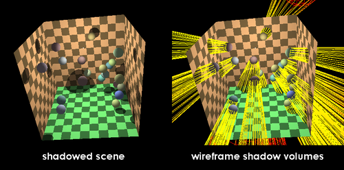
Illustration of shadow volumes. The image above at left shows a scene shadowed using shadow volumes. At right, the shadow volumes are shown in wireframe. Note how the shadows form a large conical area pointing away from the light source (the bright white point).
Stencil buffer implementations
After Crow, in 1991 Tim Heidmann showed how to use the stencil buffer to render shadows with shadow volumes quickly enough for use in real time applications. There are three common variations to this technique, depth pass, depth fail, and exclusive-or, but all of them use the same process:
Render the scene as if it were completely in shadow.
For each light source:
Using the depth information from that scene, construct a mask in the stencil buffer that has holes only where the visible surface is not in shadow.
Render the scene again as if it were completely lit, using the stencil buffer to mask the shadowed areas. Use additive blending to add this render to the scene.
The difference between these three methods occurs in the generation of the mask in the second step. Some involve two passes, and some only one; some require less precision in the stencil buffer.
Shadow volumes tend to cover large portions of the visible scene, and as a result consume valuable rasterization time (fill time) on 3D graphics hardware. This problem is compounded by the complexity of the shadow casting objects, as each object can cast its own shadow volume of any potential size onscreen. See optimization below for a discussion of techniques used to combat the fill time problem.
Depth pass
Heidmann proposed that if the front surfaces and back surfaces of the shadows were rendered in separate passes, the number of front faces and back faces in front of an object can be counted using the stencil buffer. If an object's surface is in shadow, there will be more front facing shadow surfaces between it and the eye than back facing shadow surfaces. If their numbers are equal, however, the surface of the object is not in shadow. The generation of the stencil mask works as follows:
Set the stencil operation to increment on depth pass (only count shadows in front of the object).
Render the shadow volumes (because of culling, only their front faces are rendered).
Use front-face culling.
Set the stencil operation to decrement on depth pass.
Render the shadow volumes (only their back faces are rendered).
According to Euler characteristic, all lit surfaces will correspond to a 0 in the stencil buffer, where the numbers of front and back surfaces of all closed manifolds (shadow volumes) are equal.
This approach has problems when the eye itself is inside a shadow volume (for example, when the light source moves behind an object). From this point of view, the eye sees the back face of this shadow volume before anything else, and this adds a −1 bias to the entire stencil buffer, effectively inverting the shadows. This can be remedied by adding a "cap" surface to the front of the shadow volume facing the eye, such as at the front clipping plane. There is another situation where the eye may be in the shadow of a volume cast by an object behind the camera, which also has to be capped somehow to prevent a similar problem. In most common implementations, because properly capping for depth-pass can be difficult to accomplish, the depth-fail method (see below) may be licensed for these special situations. Alternatively one can give the stencil buffer a +1 bias for every shadow volume the camera is inside, though doing the detection can be slow.
There is another potential problem if the stencil buffer does not have enough bits to accommodate the number of shadows visible between the eye and the object surface, because it uses saturation arithmetic. (If they used arithmetic overflow instead, the problem would be insignificant.)
Depth pass testing is also known as z-pass testing, as the depth buffer is often referred to as the z-buffer.
Depth fail
Around the year 2000, several people discovered that Heidmann's method can be made to work for all camera positions by reversing the depth. Instead of counting the shadow surfaces in front of the object's surface, the surfaces behind it can be counted just as easily, with the same end result. This solves the problem of the eye being in shadow, since shadow volumes between the eye and the object are not counted, but introduces the condition that the rear end of the shadow volume must be capped, or shadows will end up missing where the volume points backward to infinity.
Disable writes to the depth and color buffers.
Use front-face culling.
Set the stencil operation to increment on depth fail (only count shadows behind the object).
Render the shadow volumes.
Use back-face culling.
Set the stencil operation to decrement on depth fail.
Render the shadow volumes.
The depth fail method has the same considerations regarding the stencil buffer's precision as the depth pass method. Also, similar to depth pass, it is sometimes referred to as the z-fail method.
William Bilodeau and Michael Songy discovered this technique in October 1998, and presented the technique at Creativity, a Creative Labs developer's conference, in 1999.[2]Sim Dietrich presented this technique at both GDC in March 1999, and at Creativity in late 1999.[3][4] A few months later, William Bilodeau and Michael Songy filed a US patent application for the technique the same year entitled "Method for rendering shadows using a shadow volume and a stencil buffer".[5]John Carmack of id Software independently discovered the algorithm in 2000 during the development of Doom 3.[6] id Software was allowed to use Creative's patent in exchange for the game promoting the company's EAX audio system.[7]
Exclusive-or
Either of the above types may be approximated with an exclusive-or variation, which does not deal properly with intersecting shadow volumes, but saves one rendering pass (if not fill time), and only requires a 1-bit stencil buffer. The following steps are for the depth pass version:
Disable writes to the depth and color buffers.
Set the stencil operation to XOR on depth pass (flip on any shadow surface).
Render the shadow volumes.
Optimization
One method of speeding up the shadow volume geometry calculations is to utilize existing parts of the rendering pipeline to do some of the calculation. For instance, by using homogeneous coordinates, the w-coordinate may be set to zero to extend a point to infinity. This should be accompanied by a viewing frustum that has a far clipping plane that extends to infinity in order to accommodate those points, accomplished by using a specialized projection matrix. This technique reduces the accuracy of the depth buffer slightly, but the difference is usually negligible. See 2002 paper "Practical and Robust Stenciled Shadow Volumes for Hardware-Accelerated Rendering", C. Everitt and M. Kilgard, for a detailed implementation.
Rasterization time of the shadow volumes can be reduced by using an in-hardware scissor test to limit the shadows to a specific onscreen rectangle.
Single pass is achievable by using shader built-in variable for detecting front faces instead of two separated passes for culling each the other, combine with replacing stencil buffer with arithmetic blending on color buffer.
NVIDIA has implemented a hardware capability called the depth bounds test that is designed to remove parts of shadow volumes that do not affect the visible scene. (This has been available since the GeForce FX 5900 model.) A discussion of this capability and its use with shadow volumes was presented at the Game Developers Conference in 2005.[8]
Since the depth-fail method only offers an advantage over depth-pass in the special case where the eye is within a shadow volume, it is preferable to check for this case, and use depth-pass wherever possible. This avoids both the unnecessary back-capping (and the associated rasterization) for cases where depth-fail is unnecessary, as well as the problem of appropriately front-capping for special cases of depth-pass[citation needed].
On more recent GPU pipelines, geometry shaders can be used to generate the shadow volumes.[9][10]
On systems that do not support geometry shaders, vertex shaders can also be used to create shadow volumes by selectively extruding vertices that already reside within GPU memory.[11]
↑US 6384822,Bilodeau, William&Songy, Michael,"Method for rendering shadows using a shadow volume and a stencil buffer",published 2002-05-07, assigned to Creative Technology Ltd.
↑Kilgard, Mark; John Carmack. "John Carmack on shadow volumes..."Practical and Robust Shadow Volumes page of NVIDIA Developer Zone. archive.org: NVIDIA. Archived from the original on January 27, 2009. Retrieved 18 October 2012.
This page is based on this Wikipedia article Text is available under the CC BY-SA 4.0 license; additional terms may apply. Images, videos and audio are available under their respective licenses.