Volumetric meshes are distinct from polygon meshes in that they explicitly represent both the surface and interior region of a structure, while polygon meshes only explicitly represent the surface (the volume is implicit).
Elements
Objects created with polygon meshes must store different types of elements. These include vertices, edges, faces, polygons and surfaces. In many applications, only vertices, edges and either faces or polygons are stored. A renderer may support only 3-sided faces, so polygons must be constructed of many of these, as shown above. However, many renderers either support quads and higher-sided polygons, or are able to convert polygons to triangles on the fly, making it unnecessary to store a mesh in a triangulated form.
vertex
A position (usually in 3D space) along with other information such as color, normal vector and texture coordinates.
edge
A connection between two vertices.
face
A closed set of edges, in which a triangle face has three edges, and a quad face has four edges. A polygon is a coplanar set of faces. In systems that support multi-sided faces, polygons and faces are equivalent. However, most rendering hardware supports only 3- or 4-sided faces, so polygons are represented as multiple faces. Mathematically, a polygonal mesh may be considered an unstructured grid, or undirected graph, with additional properties of geometry, shape and topology.
surfaces
More often called smoothing groups, are useful, but not required to group smooth regions. Consider a cylinder with caps, such as a soda can. For smooth shading of the sides, all surface normals must point horizontally away from the center, while the normals of the caps must point straight up and down. Rendered as a single, Phong-shaded surface, the crease vertices would have incorrect normals. Thus, some way of determining where to cease smoothing is needed to group smooth parts of a mesh, just as polygons group 3-sided faces. As an alternative to providing surfaces/smoothing groups, a mesh may contain other data for calculating the same data, such as a splitting angle (polygons with normals above this threshold are either automatically treated as separate smoothing groups or some technique such as splitting or chamfering is automatically applied to the edge between them. Additionally, very high resolution meshes are less subject to issues that would require smoothing groups, as their polygons are so small as to make the need irrelevant. Further, another alternative exists in the possibility of simply detaching the surfaces themselves from the rest of the mesh. Renderers do not attempt to smooth edges across noncontiguous polygons.
groups
Some mesh formats contain groups, which define separate elements of the mesh, and are useful for determining separate sub-objects for skeletal animation or separate actors for non-skeletal animation.
materials
Generally materials will be defined, allowing different portions of the mesh to use different shaders when rendered.
Most mesh formats also support some form of UV coordinates which are a separate 2d representation of the mesh "unfolded" to show what portion of a two-dimensional texture map to apply to different polygons of the mesh. It is also possible for meshes to contain other such vertex attribute information such as colour, tangent vectors, weight maps to control animation, etc. (sometimes also called channels).
Vertices
UML class diagram
A vertex (plural vertices) in computer graphics is a data structure that describes at least the position of a point in 2D or 3D space on a surface. The vertices of triangles often are associated not only with spatial position but also with attributes, other values used to render the object correctly. Most attributes of a vertex represent vectors in the space to be rendered. These vectors are typically 1 (x), 2 (x, y), or 3 (x, y, z) dimensional and can include a fourth homogeneous coordinate (w). These values are given meaning by a material description. In real-time rendering these properties are used by a vertex shader or vertex pipeline. Such attributes can include:
Position
2D or 3D coordinates representing a position in space
Color
Typically diffuse or specular RGB values, either representing surface colour or precomputed lighting information.
Reflectance
of the surface at the vertex, e.g. specular exponent, metallicity, fresnel values.
These define an approximated curved surface at the location of the vertex, used for lighting calculations (such as Phong shading), normal mapping, or displacement mapping, and to control subdivision.
These define an approximated curved surface at the location of the vertex, used for lighting calculations (such as Phong shading), normal mapping, or displacement mapping, and to control subdivision.
Multiple position vectors may be specified to be blended over time, especially for facial animation.
Polygons
Polygons are used in computer graphics to compose images that are three-dimensional in appearance,[2] and are one of the most popular geometric building blocks in computer graphics.[3] Polygons are built up of vertices, and are typically used as triangles.
A model's polygons can be rendered and seen simply in a wire frame model, where the outlines of the polygons are seen, as opposed to having them be shaded. This is the reason for a polygon stage in computer animation. The polygon count refers to the number of polygons being rendered per frame.
Beginning with the fifth generation of video game consoles, the use of polygons became more common, and with each succeeding generation, polygonal models became increasingly complex.
Representations
Polygon meshes may be represented in a variety of ways, using different methods to store the vertex, edge and face data. These include:
Face-vertex meshes
A simple list of vertices, and a set of polygons that point to the vertices it uses.
in which each edge points to two vertices, two faces, and the four (clockwise and counterclockwise) edges that touch them. Winged-edge meshes allow constant time traversal of the surface, but with higher storage requirements.
which store edges, half-edges, and vertices without any reference to polygons. The polygons are implicit in the representation, and may be found by traversing the structure. Memory requirements are similar to half-edge meshes.
Corner-tables
which store vertices in a predefined table, such that traversing the table implicitly defines polygons. This is in essence the triangle fan used in hardware graphics rendering. The representation is more compact, and more efficient for retrieving polygons, but operations to change polygons are slow. Furthermore, corner-tables do not represent meshes completely. Multiple corner-tables (triangle fans) are needed to represent most meshes.
Vertex-vertex meshes
A VV mesh represents only vertices, which point to other vertices. Both the edge and the face information is implicit in the representation. However, the simplicity of the representation does not allow for many efficient operations to be performed on meshes.
Each of the representations above have particular advantages and drawbacks, further discussed in Smith (2006).[4] The choice of the data structure is governed by the application, the performance required, size of the data, and the operations to be performed. For example, it is easier to deal with triangles than general polygons, especially in computational geometry. For certain operations it is necessary to have a fast access to topological information such as edges or neighboring faces; this requires more complex structures such as the winged-edge representation. For hardware rendering, compact, simple structures are needed; thus the corner-table (triangle fan) is commonly incorporated into low-level rendering APIs such as DirectX and OpenGL.
Vertex-vertex meshes
Figure 2. Vertex-vertex meshes
Vertex-vertex meshes represent an object as a set of vertices connected to other vertices. This is the simplest representation, but not widely used since the face and edge information is implicit. Thus, it is necessary to traverse the data in order to generate a list of faces for rendering. In addition, operations on edges and faces are not easily accomplished.
However, VV meshes benefit from small storage space and efficient morphing of shape. The above figure shows a four-sided box as represented by a VV mesh. Each vertex indexes its neighboring vertices. The last two vertices, 8 and 9 at the top and bottom center of the "box-cylinder", have four connected vertices rather than five. A general system must be able to handle an arbitrary number of vertices connected to any given vertex.
For a complete description of VV meshes see Smith (2006).[4]
Face-vertex meshes
Figure 3. Face-vertex meshes
Face-vertex meshes represent an object as a set of faces and a set of vertices. This is the most widely used mesh representation, being the input typically accepted by modern graphics hardware.
Face-vertex meshes improve on VV mesh for modeling in that they allow explicit lookup of the vertices of a face, and the faces surrounding a vertex. The above figure shows the "box-cylinder" example as an FV mesh. Vertex v5 is highlighted to show the faces that surround it. Notice that, in this example, every face is required to have exactly 3 vertices. However, this does not mean every vertex has the same number of surrounding faces.
For rendering, the face list is usually transmitted to the GPU as a set of indices to vertices, and the vertices are sent as position/color/normal structures (in the figure, only position is given). This has the benefit that changes in shape, but not geometry, can be dynamically updated by simply resending the vertex data without updating the face connectivity.
Modeling requires easy traversal of all structures. With face-vertex meshes it is easy to find the vertices of a face. Also, the vertex list contains a list of faces connected to each vertex. Unlike VV meshes, both faces and vertices are explicit, so locating neighboring faces and vertices is constant time. However, the edges are implicit, so a search is still needed to find all the faces surrounding a given face. Other dynamic operations, such as splitting or merging a face, are also difficult with face-vertex meshes.
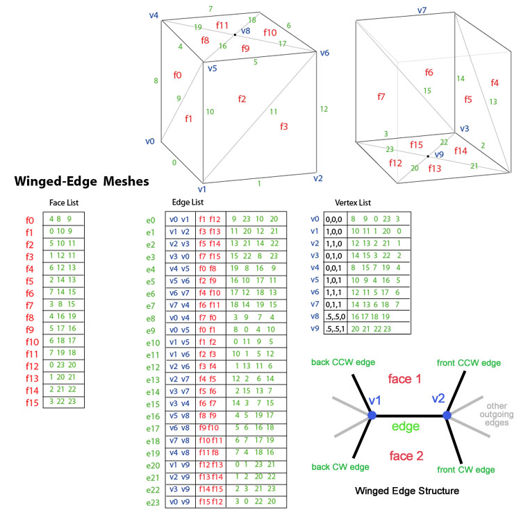
Winged-edge meshes
Figure 4. Winged-edge meshes
Introduced by Baumgart in 1975, winged-edge meshes explicitly represent the vertices, faces, and edges of a mesh. This representation is widely used in modeling programs to provide the greatest flexibility in dynamically changing the mesh geometry, because split and merge operations can be done quickly. Their primary drawback is large storage requirements and increased complexity due to maintaining many indices. A good discussion of implementation issues of Winged-edge meshes may be found in the book Graphics Gems II.
Winged-edge meshes address the issue of traversing from edge to edge, and providing an ordered set of faces around an edge. For any given edge, the number of outgoing edges may be arbitrary. To simplify this, winged-edge meshes provide only four, the nearest clockwise and counter-clockwise edges at each end. The other edges may be traversed incrementally. The information for each edge therefore resembles a butterfly, hence "winged-edge" meshes. The above figure shows the "box-cylinder" as a winged-edge mesh. The total data for an edge consists of 2 vertices (endpoints), 2 faces (on each side), and 4 edges (winged-edge).
Rendering of winged-edge meshes for graphics hardware requires generating a Face index list, which is usually done only when the geometry changes. Winged-edge meshes are ideally suited for dynamic geometry, such as subdivision surfaces and interactive modeling, since changes to the mesh can occur locally. Traversal across the mesh, as might be needed for collision detection, can be accomplished efficiently.
Winged-edge meshes are not the only representation which allows for dynamic changes to geometry. A new representation which combines winged-edge meshes and face-vertex meshes is the render dynamic mesh, which explicitly stores both, the vertices of a face and faces of a vertex (like FV meshes), and the faces and vertices of an edge (like winged-edge).
Render dynamic meshes requires slightly less storage space than standard winged-edge meshes, and can be directly rendered by graphics hardware since the face list contains an index of vertices. In addition, traversal from vertex to face is explicit (constant time), as is from face to vertex. RD meshes do not require the four outgoing edges since these can be found by traversing from edge to face, then face to neighboring edge.
RD meshes benefit from the features of winged-edge meshes by allowing for geometry to be dynamically updated.
See Tobler & Maierhofer (WSCG 2006) for more details.[6]
Summary
Summary of mesh representation
Operation
Vertex-vertex
Face-vertex
Winged-edge
Render dynamic
V-V
All vertices around vertex
Explicit
V → f1, f2, f3, ... → v1, v2, v3, ...
V → e1, e2, e3, ... → v1, v2, v3, ...
V → e1, e2, e3, ... → v1, v2, v3, ...
E-F
All edges of a face
F(a,b,c) → {a,b}, {b,c}, {a,c}
F → {a,b}, {b,c}, {a,c}
Explicit
Explicit
V-F
All vertices of a face
F(a,b,c) → {a,b,c}
Explicit
F → e1, e2, e3 → a, b, c
Explicit
F-V
All faces around a vertex
Pair search
Explicit
V → e1, e2, e3 → f1, f2, f3, ...
Explicit
E-V
All edges around a vertex
V → {v,v1}, {v,v2}, {v,v3}, ...
V → f1, f2, f3, ... → v1, v2, v3, ...
Explicit
Explicit
F-E
Both faces of an edge
List compare
List compare
Explicit
Explicit
V-E
Both vertices of an edge
E(a,b) → {a,b}
E(a,b) → {a,b}
Explicit
Explicit
Flook
Find face with given vertices
F(a,b,c) → {a,b,c}
Set intersection of v1,v2,v3
Set intersection of v1,v2,v3
Set intersection of v1,v2,v3
Storage size
V*avg(V,V)
3F + V*avg(F,V)
3F + 8E + V*avg(E,V)
6F + 4E + V*avg(E,V)
Example with 10 vertices, 16 faces, 24 edges:
10 * 5 = 50
3*16 + 10*5 = 98
3*16 + 8*24 + 10*5 = 290
6*16 + 4*24 + 10*5 = 242
Figure6: summary of mesh representation operations
In the above table, explicit indicates that the operation can be performed in constant time, as the data is directly stored; list compare indicates that a list comparison between two lists must be performed to accomplish the operation; and pair search indicates a search must be done on two indices. The notation avg(V,V) means the average number of vertices connected to a given vertex; avg(E,V) means the average number of edges connected to a given vertex, and avg(F,V) is the average number of faces connected to a given vertex.
The notation "V → f1, f2, f3, ... → v1, v2, v3, ..." describes that a traversal across multiple elements is required to perform the operation. For example, to get "all vertices around a given vertex V" using the face-vertex mesh, it is necessary to first find the faces around the given vertex V using the vertex list. Then, from those faces, use the face list to find the vertices around them. Winged-edge meshes explicitly store nearly all information, and other operations always traverse to the edge first to get additional info. Vertex-vertex meshes are the only representation that explicitly stores the neighboring vertices of a given vertex.
As the mesh representations become more complex (from left to right in the summary), the amount of information explicitly stored increases. This gives more direct, constant time, access to traversal and topology of various elements but at the cost of increased overhead and space in maintaining indices properly.
Figure 7 shows the connectivity information for each of the four technique described in this article. Other representations also exist, such as half-edge and corner tables. These are all variants of how vertices, faces and edges index one another.
As a general rule, face-vertex meshes are used whenever an object must be rendered on graphics hardware that does not change geometry (connectivity), but may deform or morph shape (vertex positions) such as real-time rendering of static or morphing objects. Winged-edge or render dynamic meshes are used when the geometry changes, such as in interactive modeling packages or for computing subdivision surfaces. Vertex-vertex meshes are ideal for efficient, complex changes in geometry or topology so long as hardware rendering is not of concern.
Other representations
Streaming meshes
store faces in an ordered, yet independent, way so that the mesh can be transmitted in pieces. The order of faces may be spatial, spectral, or based on other properties of the mesh. Streaming meshes allow a very large mesh to be rendered even while it is still being loaded.
transmit the vertex and face data with increasing levels of detail. Unlike streaming meshes, progressive meshes give the overall shape of the entire object, but at a low level of detail. Additional data, new edges and faces, progressively increase the detail of the mesh.
Normal meshes
transmit progressive changes to a mesh as a set of normal displacements from a base mesh. With this technique, a series of textures represent the desired incremental modifications. Normal meshes are compact, since only a single scalar value is needed to express displacement. However, the technique requires a complex series of transformations to create the displacement textures.
File formats
There exist many different file formats for storing polygon mesh data. Each format is most effective when used for the purpose intended by its creator. Popular formats include .fbx, .dae, .obj, and .stl. A table of some more of these formats is presented below:
A common but outdated format with hard 16-bit limits on the number of vertices and faces. Neither standardised nor well documented, but used to be a "de facto standard" for data exchange.
ASCII format describing 3D geometry. All faces' vertices are ordered counter-clockwise, making facet normals implicit. Smooth normals are specified per vertex.
XML-based, open source, royalty-free, extensible, and interoperable; also supports color, texture, and scene information. ISO Standard 19775/19776/19777
Open Source. Binary (.mesh) and ASCII (.mesh.xml) format available. Includes data for vertex animation and Morph target animation (blendshape). Skeletal animation data in separate file (.skeleton).
↑Lorensen, William E.; Cline, Harvey E. (1 August 1987). "Marching cubes: A high resolution 3D surface construction algorithm". ACM SIGGRAPH Computer Graphics. 21 (4): 163–169. CiteSeerX10.1.1.545.613. doi:10.1145/37402.37422.
↑Bailey, Kat (Apr 18, 2016). "Star Fox's History of Innovation, For Better or Worse". usgamer. Archived from the original on 2022-10-22. Retrieved 2022-07-17. Developed in part by Argonaut Software, a studio that included a young Dylan Cuthbert, it pushed the Super Nintendo to the absolute limits. It looks dated now, but at the time Star Fox's polygonal graphics were sleek and cool, and well beyond anything available on the competition
↑Bruce Baumgart, Winged-Edge Polyhedron Representation for Computer Vision. National Computer Conference, May 1975. "Use of Polyhedra in computer vision". baumgart.org. May 1975. Archived from the original on 2005-08-29. Retrieved 2005-08-29.
This page is based on this Wikipedia article Text is available under the CC BY-SA 4.0 license; additional terms may apply. Images, videos and audio are available under their respective licenses.