Usage
For almost as long as telephones have been a common feature in homes and offices, telecommunication companies have regularly been faced with a situation where demand in a particular street or area exceeds the number of physical copper pairs available from the pole to the exchange.
Until the early 1980s, this situation was often dealt with by providing shared or 'party' lines, which were connected to multiple customers. This raised privacy problems since any subscriber connected to the line could listen to (or indeed, interrupt) another subscriber's call.
With advances in the size, price, and reliability of electronic equipment, it eventually became possible to provide two normal subscriber lines over one copper pair, eliminating the need for party lines. The more modern ISDN technology based digital systems that perform this task are known in Britain by the generic name 'DACS'.
DACS works by digitising the analogue signal and sending the combined digital information for both lines over the same copper pair between the exchange and the pole. The cost of the DACS equipment is significantly less than the cost of installing additional copper pairs.
Digital Access Signalling System 2 (DASS2) is an obsolescent protocol defined by British Telecom for digital links to PSTN based on ISDN. Although still available on request, it has been superseded by ETS 300 102 ("EuroISDN").

Integrated Services Digital Network (ISDN) is a set of communication standards for simultaneous digital transmission of voice, video, data, and other network services over the digitalised circuits of the public switched telephone network. Work on the standard began in 1980 at Bell Labs and was formally standardized in 1988 in the CCITT "Red Book". By the time the standard was released, newer networking systems with much greater speeds were available, and ISDN saw relatively little uptake in the wider market. One estimate suggests ISDN use peaked at a worldwide total of 25 million subscribers at a time when 1.3 billion analog lines were in use. ISDN has largely been replaced with digital subscriber line (DSL) systems of much higher performance.
Digital subscriber line is a family of technologies that are used to transmit digital data over telephone lines. In telecommunications marketing, the term DSL is widely understood to mean asymmetric digital subscriber line (ADSL), the most commonly installed DSL technology, for Internet access.
Telephony is the field of technology involving the development, application, and deployment of telecommunication services for the purpose of electronic transmission of voice, fax, or data, between distant parties. The history of telephony is intimately linked to the invention and development of the telephone.
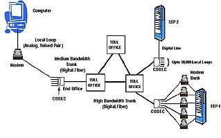
In telephony, the local loop is the physical link or circuit that connects from the demarcation point of the customer premises to the edge of the common carrier or telecommunications service provider's network.

In modern telephony a remote concentrator, remote concentrator unit (RCU), or remote line concentrator (RLC) is a concentrator at the lowest level in the telephone switch hierarchy.
Plain Old Telephone Service (POTS), or Plain Ordinary Telephone System, is a retronym for voice-grade telephone service employing analog signal transmission over copper loops. Originally POTS stood for Post Office Telephone Service as early phone lines in most parts of the world were operated directly by the local Post Office.

A digital subscriber line access multiplexer is a network device, often located in telephone exchanges, that connects multiple customer digital subscriber line (DSL) interfaces to a high-speed digital communications channel using multiplexing techniques. Its cable internet (DOCSIS) counterpart is the cable modem termination system.
ISDN Digital Subscriber Line (IDSL) uses ISDN-based digital subscriber line technology to provide a data communication channel across existing copper telephone lines at a rate of 144 kbit/s, slightly higher than a bonded dual channel ISDN connection at 128 kbit/s. The digital transmission bypasses the telephone company's central office equipment that handles analogue signals. IDSL uses the ISDN grade loop without Basic Rate Interface in ISDN transmission mode. The benefits of IDSL over ISDN are that IDSL provides always-on connections and transmits data via a data network rather than the carrier's voice network.
The public switched telephone network (PSTN) is the aggregate of the world's telephone networks that are operated by national, regional, or local telephony operators. It provides infrastructure and services for public telephony. The PSTN consists of telephone lines, fiber-optic cables, microwave transmission links, cellular networks, communications satellites, and undersea telephone cables interconnected by switching centers, such as central offices, network tandems, and international gateways, which allow telephone users to communicate with each other.
In telephony, pair gain is the transmission of multiple plain old telephone service (POTS) channels over the twisted pair local loop traditionally used for a single subscriber line in telephone systems. Pair gain has the effect of creating additional subscriber lines. This is typically used as an expedient way to solve subscriber line shortages at a location by using existing wiring, instead of installing new wires from the central office to the customer premises. The term was invented in the middle 20th century by analogy with earlier use of gain to extend telephone local loops far from the telephone exchange.

A telephone line or telephone circuit is a single-user circuit on a telephone communication system. It is designed to reproduce speech of a quality that is understandable. It is the physical wire or other signaling medium connecting the user's telephone apparatus to the telecommunications network, and usually also implies a single telephone number for billing purposes reserved for that user. Telephone lines are used to deliver landline telephone service and digital subscriber line (DSL) phone cable service to the premises. Telephone overhead lines are connected to the public switched telephone network. The voltage at a subscriber's network interface is typically 48 V between the ring and tip wires, with tip near ground and ring at –48 V.
System X is the digital switching system installed in almost all telephone exchanges throughout the United Kingdom, from 1980 onwards.

The DMS-100 is a member of the Digital Multiplex System (DMS) product line of telephone exchange switches manufactured by Northern Telecom. Designed during the 1970s and released in 1979, it can control 100,000 telephone lines.
In telecommunication, a two-wire circuit is characterized by supporting transmission in two directions simultaneously, as opposed to four-wire circuits, which have separate pairs for transmit and receive. The subscriber local loop from the telco central office are almost all two wire for analog baseband voice calls, and converted to four-wire at the line card back when telephone switching was performed on baseband audio. Today the audio is digitized and processed completely in the digital domain upstream from the local loop.
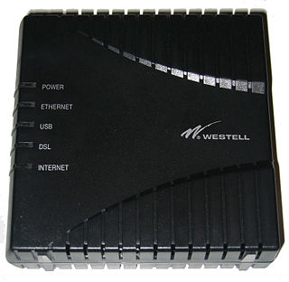
A digital subscriber line (DSL) modem is a device used to connect a computer or router to a telephone line which provides the digital subscriber line (DSL) service for connection to the Internet, which is often called DSL broadband. The modem connects to a single computer or router, through an Ethernet port, USB port, or is installed in a computer PCI slot.
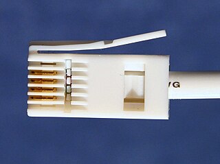
British telephone sockets were introduced in their current plug and socket form on 19 November 1981 by British Telecom to allow subscribers to connect their own telephones. The connectors are specified in British Standard BS 6312. Electrical characteristics of the telephone interface are specified by individual network operators, e.g. in British Telecom's SIN 351. Electrical characteristics required of British telephones used to be specified in BS 6305.
BT Highway was a UK retail ISDN2e service from British Telecom which was announced in November 1997 and withdrawn in February 2007. In the domestic market, it was sold as BT Home Highway and for small businesses, BT Business Highway. These names were used simply to differentiate billing schemes; the hardware for both services used the name BT Highway. Unlike regular ISDN2e service where only a digital S interface is provided BT Highway provided both digital and analogue connections simplifying migration from regular POTS service.

Asymmetric digital subscriber line (ADSL) is a type of digital subscriber line (DSL) technology, a data communications technology that enables faster data transmission over copper telephone lines than a conventional voiceband modem can provide. ADSL differs from the less common symmetric digital subscriber line (SDSL). In ADSL, bandwidth and bit rate are said to be asymmetric, meaning greater toward the customer premises (downstream) than the reverse (upstream). Providers usually market ADSL as an Internet access service primarily for downloading content from the Internet, but not for serving content accessed by others.

A telephone exchange, also known as a telephone switch or central office, is a crucial component in the public switched telephone network (PSTN) or large enterprise telecommunications systems. It facilitates the interconnection of telephone subscriber lines or digital system virtual circuits, enabling telephone calls between subscribers.

