Distributed element model

Last updated
Fig.1 Transmission line. The distributed element model applied to a transmission line. Line model Heaviside.svg
Fig.1 Transmission line. The distributed element model applied to a transmission line.
This article is an example from the domain of electrical systems, which is a special case of the more general distributed parameter systems.

In electrical engineering, the distributed element model or transmission line model of electrical circuits assumes that the attributes of the circuit (resistance, capacitance, and inductance) are distributed continuously throughout the material of the circuit. This is in contrast to the more common lumped element model, which assumes that these values are lumped into electrical components that are joined by perfectly conducting wires. In the distributed element model, each circuit element is infinitesimally small, and the wires connecting elements are not assumed to be perfect conductors; that is, they have impedance. Unlike the lumped element model, it assumes non-uniform current along each branch and non-uniform voltage along each node. The distributed model is used at high frequencies where the wavelength becomes comparable to the physical dimensions of the circuit, making the lumped model inaccurate.

Electrical engineering field of engineering that deals with electricity

Electrical engineering is a professional engineering discipline that generally deals with the study and application of electricity, electronics, and electromagnetism. This field first became an identifiable occupation in the later half of the 19th century after commercialization of the electric telegraph, the telephone, and electric power distribution and use. Subsequently, broadcasting and recording media made electronics part of daily life. The invention of the transistor, and later the integrated circuit, brought down the cost of electronics to the point they can be used in almost any household object.

Electrical network interconnection of electrical components or a model of such an interconnection, consisting of electrical elements

An electrical network is an interconnection of electrical components or a model of such an interconnection, consisting of electrical elements. An electrical circuit is a network consisting of a closed loop, giving a return path for the current. Linear electrical networks, a special type consisting only of sources, linear lumped elements, and linear distributed elements, have the property that signals are linearly superimposable. They are thus more easily analyzed, using powerful frequency domain methods such as Laplace transforms, to determine DC response, AC response, and transient response.

Capacitance ability of a body to store an electrical charge

Capacitance is the ratio of the change in an electric charge in a system to the corresponding change in its electric potential. There are two closely related notions of capacitance: self capacitance and mutual capacitance. Any object that can be electrically charged exhibits self capacitance. A material with a large self capacitance holds more electric charge at a given voltage than one with low capacitance. The notion of mutual capacitance is particularly important for understanding the operations of the capacitor, one of the three elementary linear electronic components.

Contents

Applications

The distributed element model is more accurate but more complex than the lumped element model. The use of infinitesimals will often require the application of calculus whereas circuits analysed by the lumped element model can be solved with linear algebra. The distributed model is consequently only usually applied when accuracy calls for its use. Where this point is dependent on the accuracy required in a specific application, but essentially, it needs to be used in circuits where the wavelengths of the signals have become comparable to the physical dimensions of the components. An often quoted engineering rule of thumb (not to be taken too literally because there are many exceptions) is that parts larger than one tenth of a wavelength will usually need to be analysed as distributed elements. [1]

Lumped element model simplifies the description of the behaviour of spatially distributed physical systems into a topology consisting of discrete entities that approximate the behaviour of the distributed system under certain assumptions

The lumped element model simplifies the description of the behaviour of spatially distributed physical systems into a topology consisting of discrete entities that approximate the behaviour of the distributed system under certain assumptions. It is useful in electrical systems, mechanical multibody systems, heat transfer, acoustics, etc.

Calculus is the mathematical study of continuous change, in the same way that geometry is the study of shape and algebra is the study of generalizations of arithmetic operations.

Linear algebra branch of mathematics

Linear algebra is the branch of mathematics concerning linear equations such as

Transmission lines

Transmission lines are a common example of the use of the distributed model. Its use is dictated because the length of the line will usually be many wavelengths of the circuit's operating frequency. Even for the low frequencies used on power transmission lines, one tenth of a wavelength is still only about 500 kilometres at 60 Hz. Transmission lines are usually represented in terms of the primary line constants as shown in figure 1. From this model the behaviour of the circuit is described by the secondary line constants which can be calculated from the primary ones.

Transmission line specialized cable or other structure designed to carry alternating current of radio frequency

In radio-frequency engineering, a transmission line is a specialized cable or other structure designed to conduct alternating current of radio frequency, that is, currents with a frequency high enough that their wave nature must be taken into account. Transmission lines are used for purposes such as connecting radio transmitters and receivers with their antennas, distributing cable television signals, trunklines routing calls between telephone switching centres, computer network connections and high speed computer data buses.

Primary line constants

The primary line constants are parameters that describe the characteristics of conductive transmission lines, such as pairs of copper wires, in terms of the physical electrical properties of the line. The primary line constants are only relevant to transmission lines and are to be contrasted with the secondary line constants, which can be derived from them, and are more generally applicable. The secondary line constants can be used, for instance, to compare the characteristics of a waveguide to a copper line, whereas the primary constants have no meaning for a waveguide.

The primary line constants are normally taken to be constant with position along the line leading to a particularly simple analysis and model. However, this is not always the case, variations in physical dimensions along the line will cause variations in the primary constants, that is, they have now to be described as functions of distance. Most often, such a situation represents an unwanted deviation from the ideal, such as a manufacturing error, however, there are a number of components where such longitudinal variations are deliberately introduced as part of the function of the component. A well-known example of this is the horn antenna.

Where reflections are present on the line, quite short lengths of line can exhibit effects that are simply not predicted by the lumped element model. A quarter wavelength line, for instance, will transform the terminating impedance into its dual. This can be a wildly different impedance.

Signal reflection

Signal reflection occurs when a signal is transmitted along a transmission medium, such as a copper cable or an optical fiber. Some of the signal power may be reflected back to its origin rather than being carried all the way along the cable to the far end. This happens because imperfections in the cable cause impedance mismatches and non-linear changes in the cable characteristics. These abrupt changes in characteristics cause some of the transmitted signal to be reflected. In radio frequency (RF) practice this is often measured in a dimensionless ratio known as voltage standing wave ratio (VSWR) with a VSWR bridge. The ratio of energy bounced back depends on the impedance mismatch. Mathematically, it is defined using the reflection coefficient.

Reflections of signals on conducting lines

A signal travelling along an electrical transmission line will be partly, or wholly, reflected back in the opposite direction when the travelling signal encounters a discontinuity in the characteristic impedance of the line, or if the far end of the line is not terminated in its characteristic impedance. This can happen, for instance, if two lengths of dissimilar transmission lines are joined together.

Electrical impedance intensive physical property

Electrical impedance is the measure of the opposition that a circuit presents to a current when a voltage is applied. The term complex impedance may be used interchangeably.

High frequency transistors

Fig.2. The base region of a bipolar junction transistor can be modelled as a simplified transmission line. Line model Kelvin.svg
Fig.2. The base region of a bipolar junction transistor can be modelled as a simplified transmission line.

Another example of the use of distributed elements is in the modelling of the base region of a bipolar junction transistor at high frequencies. The analysis of charge carriers crossing the base region is not accurate when the base region is simply treated as a lumped element. A more successful model is a simplified transmission line model which includes distributed bulk resistance of the base material and distributed capacitance to the substrate. This model is represented in figure 2.

Bipolar junction transistor transistor that uses both electron and hole charge carriers.In contrast,unipolar transistors such as field-effect transistors,only use one kind of charge carrier.For their operation,BJTs use 2 junctions between 2 semiconductor types,n-type and p-type

A bipolar junction transistor is a type of transistor that uses both electron and hole charge carriers. In contrast, unipolar transistors, such as field-effect transistors, only use one kind of charge carrier. For their operation, BJTs use two junctions between two semiconductor types, n-type and p-type.

In physics, a charge carrier is a particle or quasiparticle that is free to move, carrying an electric charge, especially the particles that carry electric charges in electrical conductors. Examples are electrons, ions and holes. In a conducting medium, an electric field can exert force on these free particles, causing a net motion of the particles through the medium; this is what constitutes an electric current. In different conducting media, different particles serve to carry charge:

Resistivity measurements

Fig. 3. Simplified arrangement for measuring resistivity of a bulk material with surface probes. Resistivity probes.svg
Fig. 3. Simplified arrangement for measuring resistivity of a bulk material with surface probes.

In many situations it is desired to measure resistivity of a bulk material by applying an electrode array at the surface. Amongst the fields that use this technique are geophysics (because it avoids having to dig into the substrate) and the semiconductor industry (for the similar reason that it is non-intrusive) for testing bulk silicon wafers. [2] The basic arrangement is shown in figure 3, although normally more electrodes would be used. To form a relationship between the voltage and current measured on the one hand, and the resistivity of the material on the other, it is necessary to apply the distributed element model by considering the material to be an array of infinitesimal resistor elements. Unlike the transmission line example, the need to apply the distributed element model arises from the geometry of the setup, and not from any wave propagation considerations. [3]

The model used here needs to be truly 3-dimensional (transmission line models are usually described by elements of a one-dimensional line). It is also possible that the resistances of the elements will be functions of the co-ordinates, indeed, in the geophysical application it may well be that regions of changed resistivity are the very things that it is desired to detect. [4]

Inductor windings

Fig. 4. A possible distributed element model of an inductor. A more accurate model will also require series resistance elements with the inductance elements. Inductor distributed model.svg
Fig. 4. A possible distributed element model of an inductor. A more accurate model will also require series resistance elements with the inductance elements.

Another example where a simple one-dimensional model will not suffice is the windings of an inductor. Coils of wire have capacitance between adjacent turns (and also more remote turns as well, but the effect progressively diminishes). For a single layer solenoid, the distributed capacitance will mostly lie between adjacent turns as shown in figure 4 between turns T1 and T2, but for multiple layer windings and more accurate models distributed capacitance to other turns must also be considered. This model is fairly difficult to deal with in simple calculations and for the most part is avoided. The most common approach is to roll up all the distributed capacitance into one lumped element in parallel with the inductance and resistance of the coil. This lumped model works successfully at low frequencies but falls apart at high frequencies where the usual practice is to simply measure (or specify) an overall Q for the inductor without associating a specific equivalent circuit. [5]

See also

Related Research Articles

Electrical length

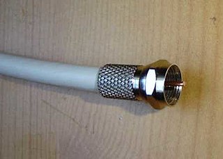
In telecommunications and electrical engineering, electrical length refers to the length of an electrical conductor in terms of the phase shift introduced by transmission over that conductor at some frequency.

Electrical elements are conceptual abstractions representing idealized electrical components, such as resistors, capacitors, and inductors, used in the analysis of electrical networks. All electrical networks can be analyzed as multiple electrical elements interconnected by wires. Where the elements roughly correspond to real components the representation can be in the form of a schematic diagram or circuit diagram. This is called a lumped element circuit model. In other cases infinitesimal elements are used to model the network in a distributed element model.

Antenna (radio) electrical device which converts electric power into radio waves, and vice versa

In radio engineering, an antenna is the interface between radio waves propagating through space and electric currents moving in metal conductors, used with a transmitter or receiver. In transmission, a radio transmitter supplies an electric current to the antenna's terminals, and the antenna radiates the energy from the current as electromagnetic waves. In reception, an antenna intercepts some of the power of a radio wave in order to produce an electric current at its terminals, that is applied to a receiver to be amplified. Antennas are essential components of all radio equipment.

Smith chart

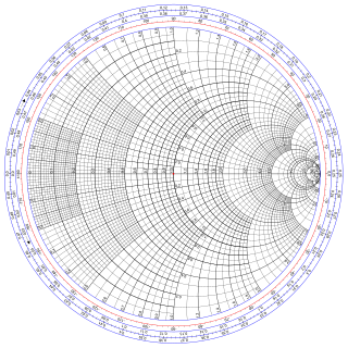
The Smith chart, invented by Phillip H. Smith (1905–1987), is a graphical aid or nomogram designed for electrical and electronics engineers specializing in radio frequency (RF) engineering to assist in solving problems with transmission lines and matching circuits. The Smith chart can be used to simultaneously display multiple parameters including impedances, admittances, reflection coefficients, scattering parameters, noise figure circles, constant gain contours and regions for unconditional stability, including mechanical vibrations analysis. The Smith chart is most frequently used at or within the unity radius region. However, the remainder is still mathematically relevant, being used, for example, in oscillator design and stability analysis.

Practical capacitors and inductors as used in electric circuits are not ideal components with only capacitance or inductance. However, they can be treated, to a very good degree of approximation, as being ideal capacitors and inductors in series with a resistance; this resistance is defined as the equivalent series resistance (ESR). If not otherwise specified, the ESR is always an AC resistance measured at specified frequencies, 100 kHz for switched-mode power supply components, 120 Hz for linear power-supply components, and at the self-resonant frequency for general-application components. Audio components may report "Q factor", incorporating ESR among other things, at 1000 Hz.

Equivalent series inductance (ESL) is an effective inductance that is used to describe the inductive part of the impedance of certain electrical components.

Stub (electronics) short electrical transmission line

In microwave and radio-frequency engineering, a stub or resonant stub is a length of transmission line or waveguide that is connected at one end only. The free end of the stub is either left open-circuit or short-circuited. Neglecting transmission line losses, the input impedance of the stub is purely reactive; either capacitive or inductive, depending on the electrical length of the stub, and on whether it is open or short circuit. Stubs may thus function as capacitors, inductors and resonant circuits at radio frequencies.

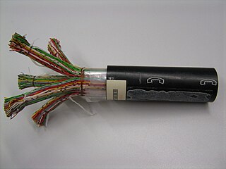
The telegrapher's equations are a pair of coupled, linear differential equations that describe the voltage and current on an electrical transmission line with distance and time. The equations come from Oliver Heaviside who in the 1880s developed the transmission line model. The model demonstrates that the electromagnetic waves can be reflected on the wire, and that wave patterns can appear along the line. The theory applies to transmission lines of all frequencies including high-frequency transmission lines, audio frequency, low frequency and direct current.

Electronic circuit electrical circuit with active components such as transistors, valves and integrated circuits; electrical network that contains active electronic components, generally nonlinear and require complex design and analysis tools

An electronic circuit is composed of individual electronic components, such as resistors, transistors, capacitors, inductors and diodes, connected by conductive wires or traces through which electric current can flow. To be referred to as electronic, rather than electrical, generally at least one active component must be present. The combination of components and wires allows various simple and complex operations to be performed: signals can be amplified, computations can be performed, and data can be moved from one place to another.

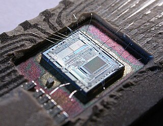
On-die termination (ODT) is the technology where the termination resistor for impedance matching in transmission lines is located inside a semiconductor chip instead of on a printed circuit board (PCB).

Distributed element filter

A distributed element filter is an electronic filter in which capacitance, inductance and resistance are not localised in discrete capacitors, inductors and resistors as they are in conventional filters. Its purpose is to allow a range of signal frequencies to pass, but to block others. Conventional filters are constructed from inductors and capacitors, and the circuits so built are described by the lumped element model, which considers each element to be "lumped together" at one place. That model is conceptually simple, but it becomes increasingly unreliable as the frequency of the signal increases, or equivalently as the wavelength decreases. The distributed element model applies at all frequencies, and is used in transmission line theory; many distributed element components are made of short lengths of transmission line. In the distributed view of circuits, the elements are distributed along the length of conductors and are inextricably mixed together. The filter design is usually concerned only with inductance and capacitance, but because of this mixing of elements they cannot be treated as separate "lumped" capacitors and inductors. There is no precise frequency above which distributed element filters must be used but they are especially associated with the microwave band.

Parasitic element (electrical networks)

In electrical networks, a parasitic element is a circuit element that is possessed by an electrical component but which it is not desirable for it to have for its intended purpose. For instance, a resistor is designed to possess resistance, but will also possess unwanted parasitic capacitance.

Mechanical filter

A mechanical filter is a signal processing filter usually used in place of an electronic filter at radio frequencies. Its purpose is the same as that of a normal electronic filter: to pass a range of signal frequencies, but to block others. The filter acts on mechanical vibrations which are the analogue of the electrical signal. At the input and output of the filter, transducers convert the electrical signal into, and then back from, these mechanical vibrations.

Commensurate line circuit

Commensurate line circuits are electrical circuits composed of transmission lines that are all the same length; commonly one-eighth of a wavelength. Lumped element circuits can be directly converted to distributed element circuits of this form by the use of Richards' transformation. This transformation has a particularly simple result; inductors are replaced with transmission lines terminated in short-circuits and capacitors are replaced with lines terminated in open-circuits. Commensurate line theory is particularly useful for designing distributed element filters for use at microwave frequencies.

The impedance analogy is a method of representing a mechanical system by an analogous electrical system. The advantage of doing this is that there is a large body of theory and analysis techniques concerning complex electrical systems, especially in the field of filters. By converting to an electrical representation, these tools in the electrical domain can be directly applied to a mechanical system without modification. A further advantage occurs in electromechanical systems: Converting the mechanical part of such a system into the electrical domain allows the entire system to be analysed as a unified whole.

Mechanical–electrical analogies are the representation of mechanical systems as electrical networks. At first, such analogies were used in reverse to help explain electrical phenomena in familiar mechanical terms. James Clerk Maxwell introduced analogies of this sort in the 19th century. However, as electrical network analysis matured it was found that certain mechanical problems could more easily be solved through an electrical analogy. Theoretical developments in the electrical domain that were particularly useful where the representation of an electrical network as an abstract topological diagram using the lumped element model and the ability of network analysis to synthesise a network to meet a prescribed frequency function.

Distributed element circuit

Distributed element circuits are electrical circuits composed of lengths of transmission lines or other distributed components. These circuits perform the same functions as conventional circuits composed of passive components, such as capacitors, inductors, and transformers. They are used mostly at microwave frequencies, where conventional components are difficult to implement.

References

  1. Kaiser, p. 3·2.
  2. Lark-Horovitz & Johnson, p. 54.
  3. Sharma, pp. 210–212.
  4. Sharma, p. 211.
  5. Northrop, pp. 141–142.

Bibliography