An amplifier, electronic amplifier or (informally) amp is an electronic device that can increase the magnitude of a signal. It is a two-port electronic circuit that uses electric power from a power supply to increase the amplitude of a signal applied to its input terminals, producing a proportionally greater amplitude signal at its output. The amount of amplification provided by an amplifier is measured by its gain: the ratio of output voltage, current, or power to input. An amplifier is defined as a circuit that has a power gain greater than one.

An operational amplifier is a DC-coupled high-gain electronic voltage amplifier with a differential input and, usually, a single-ended output. In this configuration, an op amp produces an output potential that is typically 100,000 times larger than the potential difference between its input terminals. The operational amplifier traces its origin and name to analog computers, where they were used to perform mathematical operations in linear, non-linear, and frequency-dependent circuits.

Coaxial cable, or coax, is a type of electrical cable consisting of an inner conductor surrounded by a concentric conducting shield, with the two separated by a dielectric ; many coaxial cables also have a protective outer sheath or jacket. The term coaxial refers to the inner conductor and the outer shield sharing a geometric axis.
Balanced audio is a method of interconnecting audio equipment using balanced interfaces. This type of connection is very important in sound recording and production because it allows the use of long cables while reducing susceptibility to external noise caused by electromagnetic interference. The balanced interface guarantees that induced noise appears as common-mode voltages at the receiver which can be rejected by a differential device.

In electronics, a common-base amplifier is one of three basic single-stage bipolar junction transistor (BJT) amplifier topologies, typically used as a current buffer or voltage amplifier.

A balun is an electrical device that allows balanced and unbalanced lines to be interfaced without disturbing the impedance arrangement of either line. A balun can take many forms and may include devices that also transform impedances but need not do so. Sometimes, in the case of transformer baluns, they use magnetic coupling but need not do so. Common-mode chokes are also used as baluns and work by eliminating, rather than rejecting, common mode signals.

A preamplifier, also known as a preamp, is an electronic amplifier that converts a weak electrical signal into an output signal strong enough to be noise-tolerant and strong enough for further processing, or for sending to a power amplifier and a loudspeaker. Without this, the final signal would be noisy or distorted. They are typically used to amplify signals from analog sensors such as microphones and pickups. Because of this, the preamplifier is often placed close to the sensor to reduce the effects of noise and interference.

A buffer amplifier is one that provides electrical impedance transformation from one circuit to another, with the aim of preventing the signal source from being affected by whatever currents that the load may impose. The signal is 'buffered from' load currents. In other words, a buffer turns a non-ideal voltage or current source into a "more ideal" one, that is, one with a lower internal impedance. Two main types of buffer exist: voltage buffer and current buffer.

In electrical engineering, the input impedance of an electrical network is the measure of the opposition to current (impedance), both static (resistance) and dynamic (reactance), into a load network that is external to the electrical source network. The input admittance is a measure of the load network's propensity to draw current. The source network is the portion of the network that transmits power, and the load network is the portion of the network that consumes power.
In an electrical system, a ground loop or earth loop occurs when two points of a circuit are intended to have the same ground reference potential but instead have a different potential between them. This is typically caused when enough current is flowing in the connection between the two ground points to produce a voltage drop and cause two points to be at different potentials. Current may be produced in a circular ground connection by electromagnetic induction.
This article illustrates some typical operational amplifier applications. A non-ideal operational amplifier's equivalent circuit has a finite input impedance, a non-zero output impedance, and a finite gain. A real op-amp has a number of non-ideal features as shown in the diagram, but here a simplified schematic notation is used, many details such as device selection and power supply connections are not shown. Operational amplifiers are optimised for use with negative feedback, and this article discusses only negative-feedback applications. When positive feedback is required, a comparator is usually more appropriate. See Comparator applications for further information.

A charge amplifier is an electronic current integrator that produces a voltage output proportional to the integrated value of the input current, or the total charge injected.
A radio transmitter or receiver is connected to an antenna which emits or receives the radio waves. The antenna feed system or antenna feed is the cable or conductor, and other associated equipment, which connects the transmitter or receiver with the antenna and makes the two devices compatible. In a radio transmitter, the transmitter generates an alternating current of radio frequency, and the feed system feeds the current to the antenna, which converts the power in the current to radio waves. In a radio receiver, the incoming radio waves excite tiny alternating currents in the antenna, and the feed system delivers this current to the receiver, which processes the signal.
In electronics, high impedance means that a point in a circuit allows a relatively small amount of current through, per unit of applied voltage at that point. High impedance circuits are low current and potentially high voltage, whereas low impedance circuits are the opposite. Numerical definitions of "high impedance" vary by application.

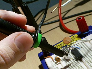
A test probe is a physical device used to connect electronic test equipment to a device under test (DUT). Test probes range from very simple, robust devices to complex probes that are sophisticated, expensive, and fragile. Specific types include test prods, oscilloscope probes and current probes. A test probe is often supplied as a test lead, which includes the probe, cable and terminating connector.
In the field of electronics, a technique where part of the output of a system is used at startup can be described as bootstrapping.

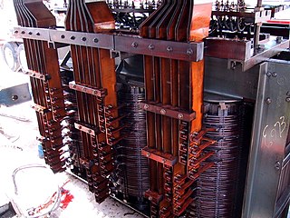
A variety of types of electrical transformer are made for different purposes. Despite their design differences, the various types employ the same basic principle as discovered in 1831 by Michael Faraday, and share several key functional parts.

Constant-voltage speaker systems refer to networks of loudspeakers which are connected to an audio amplifier using step-up and step-down transformers to simplify impedance calculations and to minimize power loss over the speaker cables. They are more appropriately called high-voltage audio distribution systems. The voltage is constant only in the sense that at full power, the voltage in the system does not depend on the number of speakers driven. Constant-voltage speaker systems are also commonly referred to as 25-, 70-, 70.7-, 100 or 210-volt speaker systems; distributed speaker systems; or high-impedance speaker systems. In Canada and the US, they are most commonly referred to as 70-volt speakers. In Europe, the 100 V system is the most widespread, with amplifier and speaker products being simply labeled with 100 V.
Isolation amplifiers are a form of differential amplifier that allow measurement of small signals in the presence of a high common mode voltage by providing electrical isolation and an electrical safety barrier. They protect data acquisition components from common mode voltages, which are potential differences between instrument ground and signal ground. Instruments that are applied in the presence of a common mode voltage without an isolation barrier allow ground currents to circulate, leading in the best case to a noisy representation of the signal under investigation. In the worst case, assuming that the magnitude of common mode voltage or current is sufficient, instrument destruction is likely. Isolation amplifiers are used in medical instruments to ensure isolation of a patient from power supply leakage current.

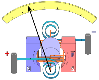
In electrical engineering, current sensing is any one of several techniques used to measure electric current. The measurement of current ranges from picoamps to tens of thousands of amperes. The selection of a current sensing method depends on requirements such as magnitude, accuracy, bandwidth, robustness, cost, isolation or size. The current value may be directly displayed by an instrument, or converted to digital form for use by a monitoring or control system.


