Electromagnetic shielding cages inside a disassembled mobile phone.
In electrical engineering, electromagnetic shielding is the practice of reducing or redirecting the electromagnetic field (EMF) in a space with barriers made of conductive or magnetic materials. It is typically applied to enclosures, for isolating electrical devices from their surroundings, and to cables to isolate wires from the environment through which the cable runs (see Shielded cable). Electromagnetic shielding that blocks radio frequency (RF) electromagnetic radiation is also known as RF shielding.
Practical field measurements in residential bedrooms typically use consumer EMF meters to determine local exposure levels.[1]
EMF shielding serves to minimize electromagnetic interference. The shielding can reduce the coupling of radio waves, electromagnetic fields, and electrostatic fields. A conductive enclosure used to block electrostatic fields is also known as a Faraday cage. The amount of reduction depends very much upon the material used, its thickness, the size of the shielded volume and the frequency of the fields of interest and the size, shape and orientation of holes in a shield to an incident electromagnetic field.
Materials used
A laptop case with visible copper electromagnetic interference (EMI) coating shield on the inside. Such coatings are usually deposited by using electroless plating. It is applied both to home appliances and medical devices.
Typical materials used for electromagnetic shielding include thin layer of metal, sheet metal, metal screen, and metal foam. Common sheet metals for shielding include copper, brass, nickel, silver, steel, and tin. Shielding effectiveness, that is, how well a shield reflects or absorbs/suppresses electromagnetic radiation, is affected by the physical properties of the metal. These may include conductivity, solderability, permeability, thickness, and weight. A metal's properties are an important consideration in material selection. For example, electrically dominant waves are reflected by highly conductive metals like copper, silver, and brass, while magnetically dominant waves are absorbed/suppressed by a less conductive metal such as steel or stainless steel.[3] Further, any holes in the shield or mesh must be significantly smaller than the wavelength of the radiation that is being kept out, or the enclosure will not effectively approximate an unbroken conducting surface.
Another commonly used shielding method, especially with electronic goods housed in plastic enclosures, is to coat the inside of the enclosure with a metallic ink or similar material. The ink consists of a carrier material loaded with a suitable metal, typically copper or nickel, in the form of very small particulates. It is sprayed on to the enclosure and, once dry, produces a continuous conductive layer of metal, which can be electrically connected to the chassis ground of the equipment, thus providing effective shielding.
Electromagnetic shielding is the process of lowering the electromagnetic field in an area by barricading it with conductive or magnetic material. Copper is used for radio frequency (RF) shielding because it absorbs radio and other electromagnetic waves. Properly designed and constructed RF shielding enclosures satisfy most RF shielding needs, from computer and electrical switching rooms to hospital CAT-scan and MRI facilities.[4][5]
EMI (electromagnetic interference) shielding is of great research interest and several new types of nanocomposites made of ferrites, polymers, and 2D materials are being developed to obtain more efficient RF/microwave-absorbing materials (MAMs).[6] EMI shielding is often achieved by electroless plating of copper as most popular plastics are non-conductive or by special conductive paint.[2]
Example of applications
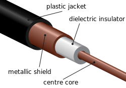
Cross-section through a coaxial cable showing shielding and other layers
One example is a shielded cable, which has electromagnetic shielding in the form of a wire mesh surrounding an inner core conductor. The shielding impedes the escape of any signal from the core conductor, and also prevents signals from being added to the core conductor. Some cables have two separate coaxial screens, one connected at both ends, the other at one end only, to maximize shielding of both electromagnetic and electrostatic fields.
The door of a microwave oven has a screen built into the window. From the perspective of microwaves (with wavelengths of 12cm) this screen finishes a Faraday cage formed by the oven's metal housing. Visible light, with wavelengths ranging between 400nm and 700nm, passes easily through the screen holes.
RF shielding is also used to prevent access to data stored on RFID chips embedded in various devices, such as biometric passports.[7]
NATO specifies electromagnetic shielding for computers and keyboards to prevent passive monitoring of keyboard emissions that would allow passwords to be captured; consumer keyboards do not offer this protection primarily because of the prohibitive cost.[8]
RF shielding is also used to protect medical and laboratory equipment to provide protection against interfering signals, including AM, FM, TV, emergency services, dispatch, pagers, ESMR, cellular, and PCS. It can also be used to protect the equipment at the AM, FM or TV broadcast facilities.
Another example of the practical use of electromagnetic shielding would be defense applications. As technology improves, so does the susceptibility to various types of nefarious electromagnetic interference. The idea of encasing a cable inside a grounded conductive barrier can provide mitigation to these risks.
Electromagnetic radiation consists of coupled electric and magnetic fields. The electric field produces forces on the charge carriers (i.e., electrons) within the conductor. As soon as an electric field is applied to the surface of an ideal conductor, it induces a current that causes displacement of charge inside the conductor that cancels the applied field inside, at which point the current stops.
Similarly, varyingmagnetic fields generate eddy currents that act to cancel the applied magnetic field. (The conductor does not respond to static magnetic fields unless the conductor is moving relative to the magnetic field.) The result is that electromagnetic radiation is reflected from the surface of the conductor: internal fields stay inside, and external fields stay outside.
Several factors serve to limit the shielding capability of real RF shields. One is that, due to the electrical resistance of the conductor, the excited field does not completely cancel the incident field. Also, most conductors exhibit a ferromagnetic response to low-frequency magnetic fields,[citation needed] so that such fields are not fully attenuated by the conductor. Any holes in the shield force current to flow around them, so that fields passing through the holes do not excite opposing electromagnetic fields. These effects reduce the field-reflecting capability of the shield.
In the case of high-frequency electromagnetic radiation, the above-mentioned adjustments take a non-negligible amount of time, yet any such radiation energy, as far as it is not reflected, is absorbed by the skin (unless it is extremely thin), so in this case there is no electromagnetic field inside either. This is one aspect of a greater phenomenon called the skin effect. A measure of the depth to which radiation can penetrate the shield is the so-called skin depth.
Magnetic shielding
Equipment sometimes requires isolation from external magnetic fields.[9] For static or slowly varying magnetic fields (below about 100kHz) the Faraday shielding described above is ineffective. In these cases shields made of high magnetic permeability metal alloys can be used, such as sheets of permalloy and mu-metal[10][11] or with nanocrystalline grain structure ferromagnetic metal coatings.[12] These materials do not block the magnetic field, as with electric shielding, but rather draw the field into themselves, providing a path for the magnetic field lines around the shielded volume. The best shape for magnetic shields is thus a closed container surrounding the shielded volume. The effectiveness of this type of shielding depends on the material's permeability, which generally drops off at both very low magnetic field strengths and high field strengths where the material becomes saturated. Therefore, to achieve low residual fields, magnetic shields often consist of several enclosures, one inside the other, each of which successively reduces the field inside it. Entry holes within shielding surfaces may degrade their performance significantly.
Because of the above limitations of passive shielding, an alternative used with static or low-frequency fields is active shielding, in which a field created by electromagnets cancels the ambient field within a volume.[13]Solenoids and Helmholtz coils are types of coils that can be used for this purpose, as well as more complex wire patterns designed using methods adapted from those used in coil design for magnetic resonance imaging. Active shields may also be designed accounting for the electromagnetic coupling with passive shields,[14][15][16][17][18] referred to as hybrid shielding,[19] so that there is broadband shielding from the passive shield and additional cancellation of specific components using the active system.
Suppose that we have a spherical shell of a (linear and isotropic) diamagnetic material with relative permeability, with inner radius and outer radius . We then put this object in a constant magnetic field: Since there are no currents in this problem except for possible bound currents on the boundaries of the diamagnetic material, then we can define a magnetic scalar potential that satisfies Laplace's equation: where In this particular problem there is azimuthal symmetry so we can write down that the solution to Laplace's equation in spherical coordinates is: After matching the boundary conditions at the boundaries (where is a unit vector that is normal to the surface pointing from side 1 to side 2), then we find that the magnetic field inside the cavity in the spherical shell is: where is an attenuation coefficient that depends on the thickness of the diamagnetic material and the magnetic permeability of the material: This coefficient describes the effectiveness of this material in shielding the external magnetic field from the cavity that it surrounds. Notice that this coefficient appropriately goes to 1 (no shielding) in the limit that . In the limit that this coefficient goes to 0 (perfect shielding). When , then the attenuation coefficient takes on the simpler form: which shows that the magnetic field decreases like .[20]
This page is based on this Wikipedia article Text is available under the CC BY-SA 4.0 license; additional terms may apply. Images, videos and audio are available under their respective licenses.