
An amplifier, electronic amplifier or (informally) amp is an electronic device that can increase the power of a signal. It is a two-port electronic circuit that uses electric power from a power supply to increase the amplitude of a signal applied to its input terminals, producing a proportionally greater amplitude signal at its output. The amount of amplification provided by an amplifier is measured by its gain: the ratio of output voltage, current, or power to input. An amplifier is a circuit that has a power gain greater than one.
A voltmeter is an instrument used for measuring electric potential difference between two points in an electric circuit. It is connected in parallel. It usually has a high resistance so that it takes negligible current from the circuit.
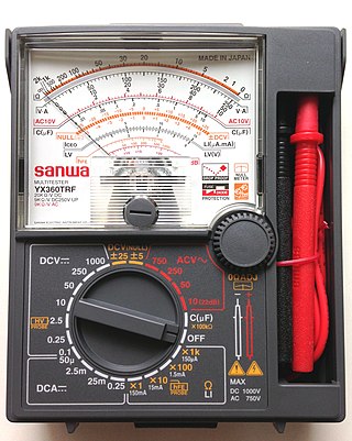
A multimeter is a measuring instrument that can measure multiple electrical properties. A typical multimeter can measure voltage, resistance, and current, in which case it is also known as a volt-ohm-milliammeter (VOM), as the unit is equipped with voltmeter, ammeter, and ohmmeter functionality, or volt-ohmmeter for short. Some feature the measurement of additional properties such as temperature and capacitance.

In electrical engineering, ground or earth is a reference point in an electrical circuit from which voltages are measured, a common return path for electric current, or a direct physical connection to the Earth.

A power supply is an electrical device that supplies electric power to an electrical load. The main purpose of a power supply is to convert electric current from a source to the correct voltage, current, and frequency to power the load. As a result, power supplies are sometimes referred to as electric power converters. Some power supplies are separate standalone pieces of equipment, while others are built into the load appliances that they power. Examples of the latter include power supplies found in desktop computers and consumer electronics devices. Other functions that power supplies may perform include limiting the current drawn by the load to safe levels, shutting off the current in the event of an electrical fault, power conditioning to prevent electronic noise or voltage surges on the input from reaching the load, power-factor correction, and storing energy so it can continue to power the load in the event of a temporary interruption in the source power.

An opto-isolator is an electronic component that transfers electrical signals between two isolated circuits by using light. Opto-isolators prevent high voltages from affecting the system receiving the signal. Commercially available opto-isolators withstand input-to-output voltages up to 10 kV and voltage transients with speeds up to 25 kV/μs.

An isolation transformer is a transformer used to transfer electrical power from a source of alternating current (AC) power to some equipment or device while isolating the powered device from the power source, usually for safety reasons or to reduce transients and harmonics. Isolation transformers provide galvanic isolation; no conductive path is present between source and load. This isolation is used to protect against electric shock, to suppress electrical noise in sensitive devices, or to transfer power between two circuits which must not be connected. A transformer sold for isolation is often built with special insulation between primary and secondary, and is specified to withstand a high voltage between windings.
Appliance classes specify measures to prevent dangerous contact voltages on unenergized parts, such as the metallic casing, of an electronic device. In the electrical appliance manufacturing industry, the following appliance classes are defined in IEC 61140 and used to differentiate between the protective-earth connection requirements of devices.
In an electrical system, a ground loop or earth loop occurs when two points of a circuit are intended to have the same ground reference potential but instead have a different potential between them. This is typically caused when enough current is flowing in the connection between the two ground points to produce a voltage drop and cause two points to be at different potentials. Current may be produced in a circular ground connection by electromagnetic induction.
In electronics, a shunt is a device that creates a low-resistance path for electric current, to allow it to pass around another point in the circuit. The origin of the term is in the verb 'to shunt' meaning to turn away or follow a different path.

A cable tester is an electronic device used to verify the electrical connections in a signal cable or other wired assembly. Basic cable testers are continuity testers that verify the existence of a conductive path between ends of the cable, and verify the correct wiring of connectors on the cable. More advanced cable testers can measure the signal transmission properties of the cable such as its resistance, signal attenuation, noise and interference.

Galvanic isolation is a principle of isolating functional sections of electrical systems to prevent current flow; no direct conduction path is permitted. Energy or information can still be exchanged between the sections by other means, such as capacitive, inductive, radiative, optical, acoustic or mechanical.

A test probe is a physical device used to connect electronic test equipment to a device under test (DUT). Test probes range from very simple, robust devices to complex probes that are sophisticated, expensive, and fragile. Specific types include test prods, oscilloscope probes and current probes. A test probe is often supplied as a test lead, which includes the probe, cable and terminating connector.
In-circuit testing (ICT) is an example of white box testing where an electrical probe tests a populated printed circuit board (PCB), checking for shorts, opens, resistance, capacitance, and other basic quantities which will show whether the assembly was correctly fabricated. It may be performed with a "bed of nails" test fixture and specialist test equipment, or with a fixtureless in-circuit test setup.
Isolation amplifiers are a form of differential amplifier that allow measurement of small signals in the presence of a high common mode voltage by providing electrical isolation and an electrical safety barrier. They protect data acquisition components from common mode voltages, which are potential differences between instrument ground and signal ground. Instruments that are applied in the presence of a common mode voltage without an isolation barrier allow ground currents to circulate, leading in the best case to a noisy representation of the signal under investigation. In the worst case, assuming that the magnitude of common mode voltage or current is sufficient, instrument destruction is likely. Isolation amplifiers are used in medical instruments to ensure isolation of a patient from power supply leakage current.

An oscilloscope is a type of electronic test instrument that graphically displays varying electrical voltages as a two-dimensional plot of one or more signals as a function of time. The main purposes are to display repetitive or single waveforms on the screen that would otherwise occur too briefly to be perceived by the human eye. The displayed waveform can then be analyzed for properties such as amplitude, frequency, rise time, time interval, distortion, and others. Originally, calculation of these values required manually measuring the waveform against the scales built into the screen of the instrument. Modern digital instruments may calculate and display these properties directly.
Most electrical circuits have a ground which is electrically connected to the Earth, hence the name "ground". The ground is said to be floating when this connection does not exist.
Automatic test system switching test equipment allows for high-speed testing of a device or devices in a test situation, where strict sequences and combinations of switching must be observed. By automating the process in this way, the possibility of test errors and inaccuracies is minimized, and only systematic errors would generally be encountered due to such as an incorrect programmed test condition. This eliminates error due to human factors and allows application of a standard test sequence repetitively. The design of a test system’s switching configuration is governed by the test specification, which is derived from the functional tests to be performed.
This glossary of electrical and electronics engineering is a list of definitions of terms and concepts related specifically to electrical engineering and electronics engineering. For terms related to engineering in general, see Glossary of engineering.