
Electric power transmission is the bulk movement of electrical energy from a generating site, such as a power plant, to an electrical substation. The interconnected lines that facilitate this movement form a transmission network. This is distinct from the local wiring between high-voltage substations and customers, which is typically referred to as electric power distribution. The combined transmission and distribution network is part of electricity delivery, known as the electrical grid.

A high-voltage direct current (HVDC) electric power transmission system uses direct current (DC) for electric power transmission, in contrast with the more common alternating current (AC) transmission systems.
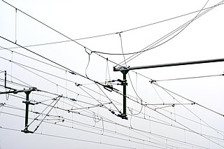
An overhead line or overhead wire is an electrical cable that is used to transmit electrical energy to electric locomotives, electric multiple units, trolleybuses or trams. The generic term used by the International Union of Railways for the technology is overhead line. It is known variously as overhead catenary, overhead contact line (OCL), overhead contact system (OCS), overhead equipment (OHE), overhead line equipment, overhead lines (OHL), overhead wiring (OHW), traction wire, and trolley wire.

Electric power distribution is the final stage in the delivery of electricity. Electricity is carried from the transmission system to individual consumers. Distribution substations connect to the transmission system and lower the transmission voltage to medium voltage ranging between 2 kV and 33 kV with the use of transformers. Primary distribution lines carry this medium voltage power to distribution transformers located near the customer's premises. Distribution transformers again lower the voltage to the utilization voltage used by lighting, industrial equipment and household appliances. Often several customers are supplied from one transformer through secondary distribution lines. Commercial and residential customers are connected to the secondary distribution lines through service drops. Customers demanding a much larger amount of power may be connected directly to the primary distribution level or the subtransmission level.

A substation is a part of an electrical generation, transmission, and distribution system. Substations transform voltage from high to low, or the reverse, or perform any of several other important functions. Between the generating station and consumer, electric power may flow through several substations at different voltage levels. A substation may include transformers to change voltage levels between high transmission voltages and lower distribution voltages, or at the interconnection of two different transmission voltages. They are a common component of the infrastructure. There are 55,000 substations in the United States.

An electric locomotive is a locomotive powered by electricity from overhead lines, a third rail or on-board energy storage such as a battery or a supercapacitor. Locomotives with on-board fuelled prime movers, such as diesel engines or gas turbines, are classed as diesel–electric or gas turbine–electric and not as electric locomotives, because the electric generator/motor combination serves only as a power transmission system.

Railway electrification is the use of electric power for the propulsion of rail transport. Electric railways use either electric locomotives, electric multiple units or both. Electricity is typically generated in large and relatively efficient generating stations, transmitted to the railway network and distributed to the trains. Some electric railways have their own dedicated generating stations and transmission lines, but most purchase power from an electric utility. The railway usually provides its own distribution lines, switches, and transformers.

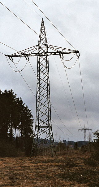
A transmission tower is a tall structure, usually a lattice tower made of steel that is used to support an overhead power line. In electrical grids, transmission towers carry high-voltage transmission lines that transport bulk electric power from generating stations to electrical substations, from which electricity is delivered to end consumers; moreover, utility poles are used to support lower-voltage sub-transmission and distribution lines that transport electricity from substations to electricity customers.

The Baltic Cable is a monopolar HVDC power line running beneath the Baltic Sea that interconnects the electric power grids of Germany and Sweden. Its maximum transmission power is 600 megawatts (MW).

The HVDC Volgograd–Donbass is a 475 kilometres (295 mi) long bipolar ±400 kV high voltage direct current powerline used for transmitting electric power from Volga Hydroelectric Station at Volgograd in Russia to Donbas in eastern Ukraine and vice versa.
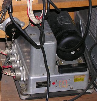
A motor–generator is a device for converting electrical power to another form. Motor–generator sets are used to convert frequency, voltage, or phase of power. They may also be used to isolate electrical loads from the electrical power supply line. Large motor–generators were widely used to convert industrial amounts of power while smaller motor–generators were used to convert battery power to higher DC voltages.
The HVDC Sileru–Barsoor is a high voltage direct current transmission system between Sileru and Barsoor in India. It is in service since 1989 as the first HVDC line in the country. The HVDC Sileru–Barsoor is a bipolar HVDC with a voltage of 200 kV and a transmission rate of 400 megawatts. The HVDC Sileru–Barsoor couples two asynchronously operated parts of Indian electricity mains over a 196 kilometres (122 mi) long overhead line, which was originally a double-circuit 220 kV AC line from which three conductors are paralleled.
A traction network or traction power network is an electricity grid for the supply of electrified rail networks. The installation of a separate traction network generally is done only if the railway in question uses alternating current (AC) with a frequency lower than that of the national grid, such as in Germany, Austria and Switzerland.

A traction substation, traction current converter plant, rectifier station or traction power substation (TPSS) is an electrical substation that converts electric power from the form provided by the electrical power industry for public utility service to an appropriate voltage, current type and frequency to supply railways, trams (streetcars) or trolleybuses with traction current.

Railway electrification systems using alternating current (AC) at 25 kilovolts (kV) are used worldwide, especially for high-speed rail. It is usually supplied at the standard utility frequency, which simplifies traction substations. The development of 25 kV AC electrification is closely connected with that of successfully using utility frequency.
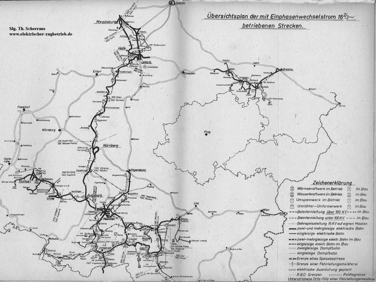
Railway electrification using alternating current (AC) at 15 kilovolts (kV) and 16.7 hertz (Hz) are used on transport railways in Germany, Austria, Switzerland, Sweden, and Norway. The high voltage enables high power transmission with the lower frequency reducing the losses of the traction motors that were available at the beginning of the 20th century. Railway electrification in late 20th century tends to use 25 kV, 50 Hz AC systems which has become the preferred standard for new railway electrifications but extensions of the existing 15 kV networks are not completely unlikely. In particular, the Gotthard Base Tunnel still uses 15 kV, 16.7 Hz electrification.

Amtrak's 25 Hz traction power system is a traction power network for the southern portion of the Northeast Corridor (NEC), the Keystone Corridor, and several branch lines between New York City and Washington D.C. The system was constructed by the Pennsylvania Railroad between 1915 and 1938 before the North American power transmission grid was fully established. This is the reason the system uses 25 Hz, as opposed to 60 Hz, which is the standard frequency for power transmission in North America. The system is also known as the Southend Electrification, in contrast to Amtrak's 60 Hz traction power system that runs between Boston and New Haven, which is known as the Northend Electrification system.

Amtrak’s 60 Hz traction power system operates along the Northeast Corridor between New Haven, Connecticut, and Boston, Massachusetts. This system was built by Amtrak in the late 1990s and supplies locomotives with power from an overhead catenary system at 25 kV alternating current with at 60 Hz, the standard frequency in North America. The system is also known as the Northend Electrification, in contrast to Amtrak's 25 Hz traction power system that runs between New York City and Washington, D.C., which is known as the Southend Electrification system.

The New York, New Haven and Hartford Railroad pioneered electrification of main line railroads using high-voltage, alternating current, single-phase overhead catenary. It electrified its mainline between Stamford, Connecticut, and Woodlawn, New York, in 1907 and extended the electrification to New Haven, Connecticut, in 1914. While single-phase AC railroad electrification has become commonplace, the New Haven's system was unprecedented at the time of construction. The significance of this electrification was recognized in 1982 by its designation as a Historic Mechanical Engineering Landmark by the American Society of Mechanical Engineers (ASME).
