Multi-system (rail)

Last updated
SNCF Class B 82500 multi-system electro-diesel multiple unit at Provins B82500 Provins5.JPG
SNCF Class B 82500 multi-system electro-diesel multiple unit at Provins

A multi-system locomotive, also known as a multi-system electric locomotive, multi-system electric multiple unit, or multi-system train, is an electric locomotive which can operate using more than one railway electrification system. Multi-system trains provide continuous journeys over routes which are electrified using more than one system.

Contents

Reasons

A multi-system locomotive is useful for providing a single journey over multiple electrification systems without interruption, either from requiring passengers to change trains or from changing locomotives. Such conditions can occur where a train crosses national boundaries and each country has implemented a different electrification system. [1]

Examples

European Union

Prior to 1945 there was no demand for multi-system locomotives in Europe. From the 1950s onwards, the emerging formation of the European Union, and the consequent increase in the amount of cross border traffic, along with the addition of a 25 kV 50 Hz AC system in France in addition to the older 1.5 kV DC system, gave rise to the need for multi-voltage locomotives. [2] Very high capital costs prevent or hinder the adoption of a standard railway electrification system. [3]

At the beginning of the 21st century, railway legislation in Europe (the First Railway Package and Second Railway Package, and the creation of a Trans European Rail Freight Network ) liberalised cross border freight traffic, giving rise to a demand for locomotives that could work between European Union countries with different electrification systems. That created a practically new market for multi-voltage locomotives, such as Bombardier's TRAXX. [4] However, the increase in the cost of locomotives and maintenance, along with the expense of installing different safety systems for cross-border work, reduced the economic viability of multi-system vehicles versus the use of single-voltage machines or changing locomotives where electrical systems change. [5]

South Africa

South Africa has 15 km (9.3 miles) of dual system track, both 3 kV DC and 25 kV AC.[ citation needed ]

South Korea

Cheongnyangni-Hoegi DC-AC neutral section at the northern tunnel entrance of Seoul Subway Line 1 Cheongnyangni-Hoegi DC-AC Deadsection with Seoul Metro 1009 Bound the Cheongnyangni.JPG
Cheongnyangni-Hoegi DC-AC neutral section at the northern tunnel entrance of Seoul Subway Line 1

Sections of track between Cheongnyangni station and Hoegi station, as well as between Seoul Station and Namyeong station on Seoul Subway Line 1, and the section of track (including the flying crossover) between Namtaeryeong station and Seonbawi station on Seoul Subway Line 4, are dual system-equipped with the subway standard 1500 V DC and mainline railway standard 25 kV 60 Hz AC overhead line systems.

United Kingdom

Between 1994 and 2007 the British Rail Class 373 could operate from 750 V DC Third rail, 25 kV AC Overhead line and 3 kV DC also through Overhead lines. The ability to run on third rail was made redundant with the moving of Eurostar services to St Pancras railway station in November 2007. Bromley South Eurostar.jpg
Between 1994 and 2007 the British Rail Class 373 could operate from 750 V DC Third rail, 25 kV AC Overhead line and 3 kV DC also through Overhead lines. The ability to run on third rail was made redundant with the moving of Eurostar services to St Pancras railway station in November 2007.

Electrification in the UK began in a piecemeal fashion. The earliest main line (as opposed to metro and tramway) systems were divided between low voltage third rail (commonly about 600 V DC) and overhead systems (a variety of voltages, both DC and AC were used). The third rail systems of this period eventually gave rise to the 750 V DC system in the southern part of the UK and a separate area with the same system around Merseyside.

Cheap loans to stimulate economic development in the 1930s gave rise to the several schemes of 1.5 kV DC electrification, mostly completed post war, notably between Liverpool Street and Shenfield, and the Woodhead Line. Starting with the West Coast Main Line electrification in the 1960s, the 25 kV AC overhead system was adopted for all subsequent mainline electrification in the UK (except for extensions to other existing systems, mostly on the southern third rail network).

In some areas with restricted clearances, particularly in urban areas in east London (converted from 1,500 V DC) and on suburban routes around Glasgow, 6.25 kV was used. A system known as "Automatic Power Control" was developed to allow trains to automatically switch between the voltages whilst moving. All the driver had to do was shut off power and coast until clear of the neutral section; the system automatically opened the circuit breaker, detected a change in voltage and switched over the transformer to the correct input voltage setting, then closed the circuit breaker. This system proved somewhat unreliable and, with experience, it was found that less clearance was needed for 25 kV than had initially been allowed for. This allowed the 6.25 kV sections to be converted to 25 kV, with the last section, at the London end of the London Tilbury and Southend line, being converted in 1983.

United States

New Haven EP-1 No. 020, circa 1907. Note the small DC pantograph between the two larger AC pantographs NH EP-1.png
New Haven EP-1 No. 020, circa 1907. Note the small DC pantograph between the two larger AC pantographs

In the United States private companies undertook electrification independently, resulting in divergent systems. Thus the New Haven EP-1 had to support three separate electrification systems: 660 V DC via third rail, 660 V via pantograph, and 11 kV 25 Hz AC via pantograph; in order to make a 27-mile (43 km) journey from the New York Central Railroad's Grand Central Terminal in New York City to its own station in Stamford, Connecticut. [6]

Multi-system operation continues to present day. New Jersey Transit uses multi-system ALP-46 and ALP-45DP locomotives (and also future Multilevel III Electric Multiple-Units) for its Midtown Direct service into New York and Amtrak uses the multi-system ACS-64 locomotives and Acela trainsets on the Northeast Corridor between Washington DC and Boston. In both cases, trains run on both newer, 25 kV 60 Hz built or refurbished by their respective agencies since the 1980s and older, 12 kV 25 Hz inherited from the now-defunct Pennsylvania Railroad. The latter dates to the 1930s, when the Pennsylvania upgraded its electrified network from 650  V DC third rail.[ citation needed ]

Metro-North Railroad utilizes M8 electric multiple units on its New Haven Line, which are capable of using 750 V DC Third Rail, 12.5 kV 60 Hz and 25 kV 60 Hz overhead electrification. Third rail electrification persists between Grand Central Terminal and Mount Vernon East, while overhead electrification exists from Pelham to New Haven. While traveling between Mount Vernon East and Pelham, trains switch between the third rail and overhead electrification systems without stopping. East of New Haven, M8s operating on Shore Line East make use of the 25 kV 60 Hz overhead electrification present.

See also

Related Research Articles

<span class="mw-page-title-main">Overhead line</span> Cable that provides power to electric railways, trams, and trolleybuses

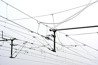
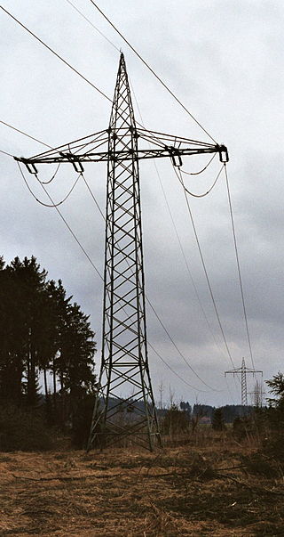
An overhead line or overhead wire is an electrical cable that is used to transmit electrical energy to electric locomotives, trolleybuses or trams. The generic term used by the International Union of Railways for the technology is overhead line. It is known variously as overhead catenary, overhead contact line (OCL), overhead contact system (OCS), overhead equipment (OHE), overhead line equipment, overhead lines (OHL), overhead wiring (OHW), traction wire, and trolley wire.

<span class="mw-page-title-main">Third rail</span> Method of providing electric power to a railway train

A third rail, also known as a live rail, electric rail or conductor rail, is a method of providing electric power to a railway locomotive or train, through a semi-continuous rigid conductor placed alongside or between the rails of a railway track. It is used typically in a mass transit or rapid transit system, which has alignments in its own corridors, fully or almost fully segregated from the outside environment. Third rail systems are usually supplied from direct current electricity.

<span class="mw-page-title-main">Electric locomotive</span> Locomotive powered by electricity

An electric locomotive is a locomotive powered by electricity from overhead lines, a third rail or on-board energy storage such as a battery or a supercapacitor. Locomotives with on-board fuelled prime movers, such as diesel engines or gas turbines, are classed as diesel-electric or gas turbine-electric and not as electric locomotives, because the electric generator/motor combination serves only as a power transmission system.

<span class="mw-page-title-main">Railway electrification</span> Conversion of railways to use electricity for propulsion

Railway electrification is the use of electric power for the propulsion of rail transport. Electric railways use either electric locomotives, electric multiple units or both. Electricity is typically generated in large and relatively efficient generating stations, transmitted to the railway network and distributed to the trains. Some electric railways have their own dedicated generating stations and transmission lines, but most purchase power from an electric utility. The railway usually provides its own distribution lines, switches, and transformers.

<span class="mw-page-title-main">Traction power network</span>

A traction network or traction power network is an electricity grid for the supply of electrified rail networks. The installation of a separate traction network generally is done only if the railway in question uses alternating current (AC) with a frequency lower than that of the national grid, such as in Germany, Austria and Switzerland.

<span class="mw-page-title-main">25 kV AC railway electrification</span> Standard current and voltage settings for most high-speed rail

Railway electrification systems using alternating current (AC) at 25 kilovolts (kV) are used worldwide, especially for high-speed rail. It is usually supplied at the standard utility frequency, which simplifies traction substations. The development of 25 kV AC electrification is closely connected with that of successfully using utility frequency.

<span class="mw-page-title-main">15 kV AC railway electrification</span> Standard current and voltage settings for much of Central Europes train transport

Railway electrification using alternating current (AC) at 15 kilovolts (kV) and 16.7 hertz (Hz) are used on transport railways in Germany, Austria, Switzerland, Sweden, and Norway. The high voltage enables high power transmission with the lower frequency reducing the losses of the traction motors that were available at the beginning of the 20th century. Railway electrification in late 20th century tends to use 25 kV, 50 Hz AC systems which has become the preferred standard for new railway electrifications but extensions of the existing 15 kV networks are not completely unlikely. In particular, the Gotthard Base Tunnel still uses 15 kV, 16.7 Hz electrification.

<span class="mw-page-title-main">Head-end power</span> Electric power supply to trains by locomotives

In rail transport, head-end power (HEP), also known as electric train supply (ETS), is the electrical power distribution system on a passenger train. The power source, usually a locomotive at the front or 'head' of a train, provides the electricity used for heating, lighting, electrical and other 'hotel' needs. The maritime equivalent is hotel electric power. A successful attempt by the London, Brighton and South Coast Railway in October 1881 to light the passenger cars on the London to Brighton route heralded the beginning of using electricity to light trains in the world.

An electro-diesel locomotive is a type of locomotive that can be powered either from an electricity supply or by using the onboard diesel engine. For the most part, these locomotives are built to serve regional, niche markets with a very specific purpose.

<span class="mw-page-title-main">British electric multiple units</span> British self-powered electric trains

An electric multiple unit (EMU) is an electric self-powered train, capable of operating in multiple with other EMUs and without the need for a locomotive; these are typically passenger trains with accommodation in every vehicle and a driving position at each end. The term can also be used to describe a train that is a permanent formation with a non-driving power car, such as the Advanced Passenger Train. As of December 2010, two-thirds of the passenger carriages in Great Britain are formed in EMUs.

<span class="mw-page-title-main">Alstom Traxx</span> Family of locomotives manufactured by Alstom, originally by Bombardier

Alstom Traxx is a modular product platform of mainline diesel-electric and electric locomotives produced originally by Bombardier Transportation and later Alstom, which was built in both freight and passenger variants. The first version was a dual-voltage AC locomotive built for German railways from the year 2000. Later types included DC versions, as well as quadruple-voltage machines, able to operate on most European electrification schemes: 1.5/3.0 kV DC and 15/25 kV AC. The family was expanded in 2006 to include diesel-powered versions. Elements common to all variants include steel bodyshells, two bogies with two powered axles each, three-phase asynchronous induction motors, cooling exhausts on the roof edges, and wheel disc brakes.

Railroad electrification in the United States began at the turn of the 20th century and comprised many different systems in many different geographical areas, few of which were connected. Despite this situation, these systems shared a small number of common reasons for electrification.

<span class="mw-page-title-main">Railway electrification in Great Britain</span> Electrification of railway lines

Railway electrification in Great Britain began in the late 19th century. A range of voltages has been used, employing both overhead lines and conductor rails. The two most common systems are 25 kV AC using overhead lines, and the 750 V DC third rail system used in Southeast England and on Merseyrail. As of March 2020, 3,758 miles (6,048 km) (38%) of the British rail network was electrified.

Railway electric traction describes the various types of locomotive and multiple units that are used on electrification systems around the world.

<span class="mw-page-title-main">Amtrak's 25 Hz traction power system</span> Unique electrical supply on the NEC

Amtrak's 25 Hz traction power system is a traction power network for the southern portion of the Northeast Corridor (NEC), the Keystone Corridor, and several branch lines between New York City and Washington D.C. The system was constructed by the Pennsylvania Railroad between 1915 and 1938 before the North American power transmission grid was fully established. This is the reason the system uses 25 Hz, as opposed to 60 Hz, which is the standard for power transmission in North America. In 1976, Amtrak inherited the system from Penn Central, the successor to the Pennsylvania Railroad, along with the rest of the NEC infrastructure.

<span class="mw-page-title-main">Amtrak's 60 Hz traction power system</span> Amtrak Northeast Corridor railroad power system

Amtrak operates a 60 Hz traction power system along the Northeast Corridor between New Haven, Connecticut, and Boston, Massachusetts. This system was built in the late 1990s and supplies locomotives with power from an overhead catenary system at 25 kV alternating current with a frequency of 60 Hz. The system is also commonly known as the Northend Electrification, in contrast to the Southend Electrification that runs between New York City and Washington, D.C.

<span class="mw-page-title-main">Electrification of the New York, New Haven and Hartford Railroad</span>

The New York, New Haven and Hartford Railroad pioneered electrification of main line railroads using high-voltage, alternating current, single-phase overhead catenary. It electrified its mainline between Stamford, Connecticut, and Woodlawn, New York, in 1907 and extended the electrification to New Haven, Connecticut, in 1914. While single-phase AC railroad electrification has become commonplace, the New Haven's system was unprecedented at the time of construction. The significance of this electrification was recognized in 1982 by its designation as a Historic Mechanical Engineering Landmark by the American Society of Mechanical Engineers (ASME).

<span class="mw-page-title-main">Baldwin-Westinghouse electric locomotives</span>

Baldwin, the locomotive manufacturer, and Westinghouse, the promoter of AC electrification, joined forces in 1895 to develop AC railway electrification. Soon after the turn of the century, they marketed a single-phase high-voltage system to railroads. From 1904 to 1905 they supplied locomotives carrying a joint builder's plate to a number of American railroads, particularly for the New Haven line from New York to New Haven, and other New Haven lines. Westinghouse would produce the motors, controls, and other electrical gear, while Baldwin would produce the running gear, frame, body, and perform final assembly.

<span class="mw-page-title-main">South African Class 20E</span>

The Transnet Freight Rail Class 20E of 2013 is a South African electric locomotive.

References

  1. "Traxx locomotive family meets European needs". Railway Gazette International. 2008-01-07. Retrieved 2011-01-01. Traxx MS (multi-system) for operation on both AC (15 and 25 kV) and DC (1.5 and 3 kV) networks
  2. Andreas Steimel (2007). "8. Multi-system traction vehicles". Electric Traction - Motion Power and Energy Supply. Oldenbourg Industrieverlag. p. 129. ISBN   9783835631328.
  3. Hans-Jörg Bullinger (2009). "7. Mobility and Transport". Technology Guide: Principles, Applications, Trends. Springer. p. 295. ISBN   9783540885467.
  4. Robert Wright (22 September 2008). "Multi-system: Competition improved by crossborder locomotives". www.ft.com. Financial Times.
  5. Pamela Luică (26 April 2011). "Multi-system locomotives, still too expensive for operators". www.railwaypro.com. Railway Pro.
  6. Middleton, William D. (2001) [1974]. When the Steam Railroads Electrified (2nd ed.). Bloomington, Indiana: Indiana University Press. pp. 77–79. ISBN   978-0-253-33979-9.