Minimum control speeds

Last updated

The minimum control speed (VMC) of a multi-engine aircraft (specifically an airplane) is a V-speed that specifies the calibrated airspeed below which directional or lateral control of the aircraft can no longer be maintained, after the failure of one or more engines. The VMC only applies if at least one engine is still operative, and will depend on the stage of flight. Indeed, multiple VMCs have to be calculated for landing, air travel, and ground travel, and there are more still for aircraft with four or more engines. These are all included in the aircraft flight manual of all multi-engine aircraft. When design engineers are sizing an airplane's vertical tail and flight control surfaces, they have to take into account the effect this will have on the airplane's minimum control speeds.

Contents

Minimum control speeds are typically established by flight tests [1] [2] [3] as part of an aircraft certification process. [4] [5] They provide a guide to the pilot in the safe operation of the aircraft.

Physical description

The most important forces and moments acting on the aircraft while using the rudder to counteract the asymmetrical thrust and while keeping the wings level. Notice a sideslip cannot be avoided for when the yawing moment is being counteracted. Vmc Article Fig 3 - Forces and moments during wings-level equilibrium.png
The most important forces and moments acting on the aircraft while using the rudder to counteract the asymmetrical thrust and while keeping the wings level. Notice a sideslip cannot be avoided for when the yawing moment is being counteracted.

When an engine on a multi-engine aircraft fails, the thrust distribution on the aircraft becomes asymmetrical, resulting in a yawing moment in the direction of the failed engine. [6] A sideslip develops, causing the total drag of the aircraft to increase considerably, resulting in a drop in the aircraft's rate of climb. [7] The rudder, and to a certain extent the ailerons via the use of bank angle, are the only aerodynamic controls available to the pilot to counteract the asymmetrical thrust yawing moment[ citation needed ].

The higher the speed of the aircraft, the easier it is to counteract the yawing moment using the aircraft's controls. [8] The minimum control speed is the airspeed below which the force the rudder or ailerons can apply to the aircraft is not large enough to counteract the asymmetrical thrust at a maximum power setting. Above this speed it should be possible to maintain control of the aircraft and maintain straight flight with asymmetrical thrust. [4]

Loss of engine power of wing-mounted-propeller aircraft and blown lift aircraft affects the lift distribution over the wing, causing a roll toward the inoperative engine. [9] [10] [3] In some aircraft roll authority is more limiting than rudder authority in determining VMCs. [11]

Certification and variants

Fig. 1. Overview of all existing minimum control speeds VMC for all multi-engine aircraft types. In this article, VMC(A) is used rather than VMC for air minimum control speeds. Vmc Article Fig 1 - Overview of all Vmc's.png
Fig. 1. Overview of all existing minimum control speeds VMC for all multi-engine aircraft types. In this article, VMC(A) is used rather than VMC for air minimum control speeds.

Aviation regulations (such as FAR and EASA) [4] [5] define several different VMCs and require design engineers to size the vertical tail and the aerodynamic flight controls of the aircraft to comply with these regulations. The minimum control speed in the air (VMCA) is the most important minimum control speed of a multi-engine aircraft, which is why VMCA is simply listed as VMC in many aviation regulations and aircraft flight manuals. [4] [5] On the airspeed indicator of a twin-engine aircraft of less than 6000 lbs (2722 kg), the VMCA is indicated by a red radial line, as standardised by FAR 23. [4] [5]

Most test pilot schools use multiple, more specific minimum control speeds, as VMC will change depending on the stage of flight. Other defined VMCs include minimum control speed on the ground (VMCG) and minimum control speed during approach and landing (VMCL). In addition, with aircraft with four or more engines, VMCs exist for cases with either one or two engines inoperative on the same wing. Figure 1 illustrates the VMCs that are defined in the relevant civil aviation regulations [4] [5] and in military specifications. [12]

Minimum control speed when airborne

The effect of bank angle on VMCA and sideslip when the left engine (No. 1) is inoperative and the other is at maximum thrust. The bank angle for zero sideslip is used for sizing the vertical tail and also during flight-testing to determine VMCA in-flight. Vmc Article Fig 5 - Graph Vmc and sideslip.png
The effect of bank angle on VMCA and sideslip when the left engine (No. 1) is inoperative and the other is at maximum thrust. The bank angle for zero sideslip is used for sizing the vertical tail and also during flight-testing to determine VMCA in-flight.

The vertical tail or vertical stabilizer of a multi-engine aircraft plays a crucial role in maintaining directional control while an engine fails or is inoperative. The larger the tail, the more capable it will be of providing the required force to counteract the asymmetrical thrust yawing moment. This means that the smaller the tail is, the higher the VMCA will be. However, a larger tail is more costly and harder to accommodate, and comes with other aerodynamic issues such as increased prevalence of slipstreams. Engineers designing the vertical tail must make a decision based on, amongst other factors, their budget, the weight of the aircraft, and the maximum bank angle of 5° (away from the inoperative engine), as stated by FAR. [4] [5]

VMCA is also used to calculate the minimum takeoff safety speed. [4] [5] A high VMCA therefore results in higher takeoff speeds, and so longer runways are required, which is undesirable for airport operators.

Factors influencing minimum control speed

Any factor that has influence on the balance of forces and on the yawing and rolling moments after engine failure might also affect VMCs. When the vertical tail is designed and the VMCA is measured, the worst-case scenario for all factors is taken into account. This ensures that the VMCs published in the AFMs guaranteed to be safe.

Heavier aircraft are more stable and more resistant to yawing moments, and therefore have lower VMCAs. [13] :13 The longitudinal centre of gravity affects the VMCA as well: the further from the tail it is, the lower the minimum control speed, because the rudder will be able to provide a larger yawing moment, and so it is easier to counteract the imbalance in thrust. [13] :17 The lateral centre of gravity also has an effect: the nearer the inoperative engine it is, the larger the moment of the working engine, and so the more force the rudder has to apply. This means that if the lateral centre of gravity shifts towards the inoperative engine, the aircraft's VMCA will increase. [13] :17 The thrust of most engines depends on altitude and temperature; increasing altitude and higher temperatures decrease thrust. This means that if the air temperature is higher and the aircraft has a higher altitude, the force of the operative engine will be lower, the rudder will have to provide less counteractive force, and so the VMCA will be lower. [13] :16 The bank angle also influences the minimum control speed. A small bank angle away from the inoperative engine is required for smallest possible sideslip and therefore lower VMCA. Finally, if the P-factor of the working engine increases, then its yawing moment increases, and the aircraft's VMCA increases as a result. [13] :15

Other minimal control speeds

Aircraft with more engines

Aircraft with four or more engines have not only a VMCA (often called VMCA1 under these circumstances), where the critical engine alone is inoperative, but also a VMCA2 that applies when the engine inboard of the critical engine, on the same wing, is also inoperative. [13] :15 Civil aviation regulations (FAR, CS and equivalent) no longer require a VMCA2 to be determined, [4] [5] although it is still required for military aircraft with four or more engines. [12] On turbojet and turbofan aircraft, the outboard engines are usually equally critical. Three-engine aircraft such as the MD-11 and BN-2 Trislander do not have a VMCA2; a failed centerline engine has no effect on VMC.

When two opposing engines of aircraft with four or more engines are inoperative, there is no thrust asymmetry, hence there is no rudder requirement for maintaining steady straight flight; VMCAs play no role. There may be less power available to maintain flight overall, but the minimum safe control speeds remain the same as they would be for an aircraft being flown at 50% thrust on all four engines.

Failure of a single inboard engine, from a set of four, has a much smaller effect on controllability. This is because an inboard engine is closer to the aircraft's centre of gravity, so the lack of yawing moment is decreased. In this situation, if speed is maintained at or above the published VMCA, as determined for the critical engine, safe control can be maintained.

Ground

If an engine fails during taxiing or takeoff, the thrust yawing moment will force the aircraft to one side on the runway. If the airspeed is not high enough and hence, the rudder-generated side force is not powerful enough, the aircraft will deviate from the runway centerline and may even veer off the runway. [13] :21 The airspeed at which the aircraft, after engine failure, deviates 9.1 m from the runway centerline, despite using maximum rudder but without the use of nose wheel steering, is the minimum control speed on the ground (VMCG). [4] [5]

Approach and landing

The minimum control speed during approach and landing (VMCL) is similar to VMCA, but the aircraft configuration is the landing configuration. VMCL is defined for both part 23 <FAR 23.149 (c)> and part 25 aircraft in civil aviation regulations. [4] [5] However, when maximum thrust is selected for a go-around, the flaps will be selected up from the landing position, and VMCL no longer applies, but VMCA does.

Safe single-engine speed


Due to the inherent risks of operating at or close to VMCA with asymmetric thrust, and the desire to simulate and practise these manoeuvres in pilot training and certification VSSE may be defined. [14] VSSE safe single-engine speed is the minimum speed to intentionally render the critical engine inoperative, established and designated by the manufacturer as the safe, intentional, one engine inoperative speed. [4] This speed is selected to reduce the accident potential from loss of control due to simulated engine failures at inordinately slow airspeed. [15]

Related Research Articles

Stall (fluid dynamics) Abrupt reduction in lift due to flow separation

In fluid dynamics, a stall is a reduction in the lift coefficient generated by a foil as angle of attack increases. This occurs when the critical angle of attack of the foil is exceeded. The critical angle of attack is typically about 15°, but it may vary significantly depending on the fluid, foil, and Reynolds number.

Landing Transition from being in flight to being on a surface

Landing is the last part of a flight, where a flying animal, aircraft, or spacecraft returns to the ground. When the flying object returns to water, the process is called alighting, although it is commonly called "landing", "touchdown" or "splashdown" as well. A normal aircraft flight would include several parts of flight including taxi, takeoff, climb, cruise, descent and landing.

Aviation is the design, development, production, operation, and use of aircraft, especially heavier-than-air aircraft. Articles related to aviation include:

Airspeed indicator Flight instrument

The airspeed indicator (ASI) or airspeed gauge is a flight instrument indicating the airspeed of an aircraft in kilometers per hour (km/h), knots (kn), miles per hour (MPH) and/or meters per second (m/s). The recommendation by ICAO is to use km/h, however knots is currently the most used unit. The ASI measures the pressure differential between static pressure from the static port, and total pressure from the pitot tube. This difference in pressure is registered with the ASI pointer on the face of the instrument.

Spin (aerodynamics) Aviation term for a corkscrew downward path

In flight dynamics a spin is a special category of stall resulting in autorotation about the aircraft's longitudinal axis and a shallow, rotating, downward path approximately centred on a vertical axis. Spins can be entered intentionally or unintentionally, from any flight attitude if the aircraft has sufficient yaw while at the stall point. In a normal spin, the wing on the inside of the turn stalls while the outside wing remains flying. It is possible for both wings to stall, but the angle of attack of each wing, and consequently its lift and drag, are different.

Flight control surfaces Surface that allows a pilot to adjust and control an aircrafts flight attitude

Aircraft flight control surfaces are aerodynamic devices allowing a pilot to adjust and control the aircraft's flight attitude.

With respect to aircraft performance, a ceiling is the maximum density altitude an aircraft can reach under a set of conditions, as determined by its flight envelope.

Rockwell-MBB X-31 Type of aircraft

The Rockwell-Messerschmitt-Bölkow-Blohm X-31 was an experimental jet fighter designed to test fighter thrust vectoring technology.

Aircraft flight mechanics are relevant to fixed wing and rotary wing (helicopters) aircraft. An aeroplane, is defined in ICAO Document 9110 as, "a power-driven heavier than air aircraft, deriving its lift chiefly from aerodynamic reactions on surface which remain fixed under given conditions of flight".

Trim tab Boat or aircraft component

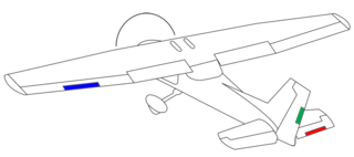
Trim tabs are small surfaces connected to the trailing edge of a larger control surface on a boat or aircraft, used to control the trim of the controls, i.e. to counteract hydro- or aerodynamic forces and stabilise the boat or aircraft in a particular desired attitude without the need for the operator to constantly apply a control force. This is done by adjusting the angle of the tab relative to the larger surface.

Vertical stabilizer Aircraft component

A vertical stabilizer or tail fin is the static part of the vertical tail of an aircraft. The term is commonly applied to the assembly of both this fixed surface and one or more movable rudders hinged to it. Their role is to provide control, stability and trim in yaw. It is part of the aircraft empennage, specifically of its stabilizers.

The critical engine of a multi-engine fixed-wing aircraft is the engine that, in the event of failure, would most adversely affect the performance or handling abilities of an aircraft. On propeller aircraft, there is a difference in the remaining yawing moments after failure of the left or the right (outboard) engine when all propellers rotate in the same direction due to the P-factor. On turbojet and turbofan twin-engine aircraft, there usually is no difference between the yawing moments after failure of a left or right engine in no-wind condition.
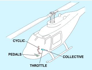
Helicopter flight controls Instruments used in helicopter flight

A helicopter pilot manipulates the helicopter flight controls to achieve and maintain controlled aerodynamic flight. Changes to the aircraft flight control system transmit mechanically to the rotor, producing aerodynamic effects on the rotor blades that make the helicopter move in a deliberate way. To tilt forward and back (pitch) or sideways (roll) requires that the controls alter the angle of attack of the main rotor blades cyclically during rotation, creating differing amounts of lift (force) at different points in the cycle. To increase or decrease overall lift requires that the controls alter the angle of attack for all blades collectively by equal amounts at the same time, resulting in ascent, descent, acceleration and deceleration.

Aircraft upset is a dangerous condition in aircraft operations in which the flight attitude or airspeed of an aircraft is outside the normal bounds of operation for which it is designed. This may result in the loss of control (LOC) of the aircraft, and sometimes the total loss of the aircraft itself. Loss of control may be due to excessive altitude for the airplane's weight, turbulent weather, pilot disorientation, or a system failure.

P-factor Yawing force caused by a rotating propeller

P-factor, also known as asymmetric blade effect and asymmetric disc effect, is an aerodynamic phenomenon experienced by a moving propeller, where the propeller's center of thrust moves off-center when the aircraft is at a high angle of attack. This shift in the location of the center of thrust will exert a yawing moment on the aircraft, causing it to yaw slightly to one side. A rudder input is required to counteract the yawing tendency.

Yaw string Device for indicating a slip or skid in an aircraft in flight

The yaw string, also known as a slip string, is a simple device for indicating a slip or skid in an aircraft in flight. It performs the same function as the slip-skid indicator ball, but is more sensitive, and does not require the pilot to look down at the instrument panel. Technically, it measures sideslip angle, not yaw angle, but this indicates how the aircraft must be yawed to return the sideslip angle to zero.

Aircraft principal axes Principal directions in aviation

An aircraft in flight is free to rotate in three dimensions: yaw, nose left or right about an axis running up and down; pitch, nose up or down about an axis running from wing to wing; and roll, rotation about an axis running from nose to tail. The axes are alternatively designated as vertical, lateral, and longitudinal respectively. These axes move with the vehicle and rotate relative to the Earth along with the craft. These definitions were analogously applied to spacecraft when the first manned spacecraft were designed in the late 1950s.

V speeds Standard terms to define airspeeds

In aviation, V-speeds are standard terms used to define airspeeds important or useful to the operation of all aircraft. These speeds are derived from data obtained by aircraft designers and manufacturers during flight testing for aircraft type-certification. Using them is considered a best practice to maximize aviation safety, aircraft performance, or both.

Loss of tail-rotor effectiveness Potential dangerous event during helicopter flight

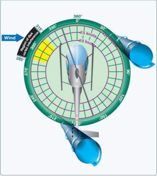
Loss of tail-rotor effectiveness (LTE) occurs when the tail rotor of a helicopter is exposed to wind forces that prevent it from carrying out its function—that of cancelling the torque of the engine and transmission. Any low-airspeed high-power environment provides an opportunity for it to occur.

Several aviation incidents and accidents have occurred in which the control surfaces of the aircraft became disabled, often due to failure of hydraulic systems or the flight control system. Other incidents have occurred where controls were not functioning correctly prior to take-off, either due to maintenance or pilot error, and controls can become inoperative from extreme weather conditions. Aircraft are not designed to be flown in such circumstances; however, a small number of pilots have had some success in flying and landing aircraft with disabled controls.

References

  1. USAF Test Pilot School, Edwards Air Force Base, CA, USA (1992). Engine-Out Theory, Chapter 11 (PDF). Archived (PDF) from the original on June 10, 2016. Retrieved May 15, 2016.{{cite book}}: CS1 maint: multiple names: authors list (link)
  2. Empire Test Pilots' School, Boscombe Down, UK. Flight on Asymmetric Power.{{cite book}}: CS1 maint: multiple names: authors list (link)
  3. 1 2 USNaval Test Pilot School. Flight Test Manual USNTPS-FTM-No. 103, Fixed Wing Stability And Control, Theory and Flight Test Techniques, Chapter 6 – Asymmetric Power Flying Qualities (PDF). Retrieved May 15, 2016.
  4. 1 2 3 4 5 6 7 8 9 10 11 12 Federal Aviation Administration, USA. "Federal Aviation Regulations (FAR)". Part 23 and Part 25, § 149. Retrieved May 15, 2016.
  5. 1 2 3 4 5 6 7 8 9 10 European Aviation Safety Agency. "Certification Specifications (CS)". CS-23 and CS-25, § 149. Retrieved Oct 28, 2013.
  6. "FAA P-8740-66 Flying Light Twin Safely": 2.{{cite journal}}: Cite journal requires |journal= (help)
  7. "Airplane Flying Handbook (FAA-H-8083-3B) Chapter 12" (PDF): 24.{{cite journal}}: Cite journal requires |journal= (help)
  8. "Airplane Flying Handbook (FAA-H-8083-3B) Chapter 6" (PDF): 3.{{cite journal}}: Cite journal requires |journal= (help)
  9. "Airplane Flying Handbook (FAA-H-8083-3B) Chapter 12" (PDF): 24.{{cite journal}}: Cite journal requires |journal= (help)
  10. USAF Test Pilot School, Edwards Air Force Base, CA, USA (1992). Engine-Out Theory, Chapter 11 (PDF). Archived (PDF) from the original on June 10, 2016. Retrieved May 15, 2016.{{cite book}}: CS1 maint: multiple names: authors list (link)
  11. USAF Test Pilot School, Edwards Air Force Base, CA, USA (1992). Engine-Out Theory, Chapter 11 (PDF). Archived (PDF) from the original on June 10, 2016. Retrieved May 15, 2016.{{cite book}}: CS1 maint: multiple names: authors list (link)
  12. 1 2 Military Specification MIL-F-8785C, superseded by MIL-STD-1797. Flying Qualities of Piloted Airplanes.
  13. 1 2 3 4 5 6 7 Horlings, Harry (January 2012). "Control and Performance during Asymmetrical Powered Flight" (PDF). Retrieved 31 March 2017.
  14. "FAA-P-8740-19-Flying Light Twins Safely" (PDF): 45.{{cite journal}}: Cite journal requires |journal= (help)
  15. "FAA P-8740-66 Flying Light Twin Safely": 6.{{cite journal}}: Cite journal requires |journal= (help)