"Test flight" redirects here. For the software QA service, see TestFlight.
Flight testing is a branch of aeronautical engineering that develops technologies and equipment required for in-flight evaluation of behaviour of an aircraft or launch vehicles and reusablespacecraft at the atmospheric phase of flight. Instrumentation systems for flight testing are developed using specialized transducers and data acquisition systems. Data is sampled during the flight of an aircraft, or atmospheric testing of spacecraft. This data is validated for accuracy and analyzed to further modify the vehicle design during development, or to validate the design of the vehicle.
The flight test phase accomplishes two major tasks: 1) finding and fixing aircraft design problems and then 2) verifying and documenting the vehicle capabilities when the vehicle design is complete, or to provide a final specification for government certification or customer acceptance. The flight test phase can range from the test of a single new system for an existing vehicle to the complete development and certification of a new aircraft, launch vehicle, or reusable spacecraft. Therefore, the duration of a particular flight test program can vary from a few weeks to years.
Aircraft flight test
Civil aircraft
There are typically two categories of flight test programs – commercial and military. Commercial flight testing is conducted to certify that the aircraft meets all applicable safety and performance requirements of the government certifying agency. In the United States, this is the Federal Aviation Administration (FAA); in Canada, Transport Canada (TC); in the United Kingdom (UK), the Civil Aviation Authority; and in the European Union, the European Aviation Safety Agency (EASA). Since commercial aircraft development is normally funded by the aircraft manufacturer and/or private investors, the certifying agency does not have a stake in the commercial success of the aircraft. These civil agencies are concerned with the aircraft's safety and that the pilot's flight manual accurately reports the aircraft's performance. The market will determine the aircraft's suitability to operators. Normally, the civil certification agency does not get involved in flight testing until the manufacturer has found and fixed any development issues and is ready to seek certification.
Military aircraft
Military programs differ from commercial in that the government contracts with the aircraft manufacturer to design and build an aircraft to meet specific mission capabilities. These performance requirements are documented to the manufacturer in the aircraft specification and the details of the flight test program (among many other program requirements) are spelled out in the statement of work. In this case, the government is the customer and has a direct stake in the aircraft's ability to perform the mission. Since the government is funding the program, it is more involved in the aircraft design and testing from early-on. Often military test pilots and engineers are integrated as part of the manufacturer's flight test team, even before first flight. The final phase of the military aircraft flight test is the Operational Test (OT). OT is conducted by a government-only test team with the dictate to certify that the aircraft is suitable and effective to carry out the intended mission.[citation needed]
Flight testing of military aircraft is often conducted at military flight test facilities. The US Navy tests aircraft at Naval Air Station Patuxent River and the US Air Force at Edwards Air Force Base. The U.S. Air Force Test Pilot School and the U.S. Naval Test Pilot School are the programs designed to teach military test personnel. In the UK, most military flight testing is conducted by three organizations, the RAF, BAE Systems and QinetiQ. For minor upgrades the testing may be conducted by one of these three organizations in isolation, but major programs are normally conducted by a joint trials team (JTT), with all three organizations working together under the umbrella of an integrated project team (IPT) airspace.[citation needed]
Atmospheric flight testing of launch vehicles and reusable spacecraft
Thermal imaging of the controlled-descent flight test of the Falcon 9 first stage from stage separation onward, on Falcon 9 Flight 13, 21 September 2014. Includes footage as the first stage maneuvers out of the second stage plume; coasting near peak altitude of approximately 140km (87mi); boost-back burn to limit downrange translation; preparing for the reentry burn; and the reentry burn from approximately 70km (43mi) to 40km (25mi) altitude. Does not include the landing burn near the ocean surface as clouds obscured the infrared imaging at low altitude.
All launch vehicles, as well as a few reusable spacecraft, must necessarily be designed to deal with aerodynamic flight loads while moving through the atmosphere.
Flight testing—typically as a class of non-revenue producing flight, although SpaceX has also done extensive flight tests on the post-mission phase of a returning booster flight on revenue launches—can be subject to the latter's statistically demonstrated higher risk of accidents or serious incidents. This is mainly due to the unknowns of a new aircraft or launch vehicle's handling characteristics and lack of established operating procedures, and can be exacerbated if test pilot training or experience of the flight crew is lacking[4] For this reason, flight testing is carefully planned in three phases: preparation; execution; and analysis and reporting.
Preparation
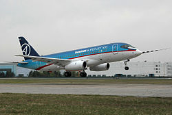
Static pressure probe on the nose of a Sukhoi Superjet 100 prototypePressure measurement equipment and water tanks in Boeing 747-8I prototypeStatic pressure probe rig aboard Boeing 747-8I prototype; a long plastic tube, shown wound round a storage drum, is connected to a probe with static pressure orifices. The probe is trailed about two wing spans behind the aircraft.
For both commercial and military aircraft, as well as launch vehicles, flight test preparation begins well before the test vehicle is ready to fly. Initially what needs to be tested must be defined, from which the Flight Test Engineers prepare the test plan, which is essentially certain maneuvers to be flown (or systems to be exercised). Each single test is known as a Test Point. A full certification/qualification flight test program for a new aircraft will require testing for many aircraft systems and in-flight regimes; each is typically documented in a separate test plan. Altogether, a certification flight test program will consist of approximately 10,000 Test Points.[citation needed]
The document used to prepare a single test flight for an aircraft is known as a Test Card. This will consist of a description of the Test Points to be flown. The flight test engineer will try to fly similar Test Points from all test plans on the same flights, where practical. This allows the required data to be acquired in the minimum number of flight hours. The software used to control the flight test process is known as Flight Test Management Software, and supports the Flight Test Engineer in planning the test points to be flown as well as generating the required documentation.[citation needed]
Once the flight test data requirements are established, the aircraft or launch vehicle is instrumented with a data acquisition system (DAS), or data acquisition unit (DAU) and sensors, to record that data for analysis. Typical instrumentation parameters recorded during a flight test for a large aircraft are:
Accelerations in all six degrees of freedom, measured with accelerometers at different positions in the aircraft;
Noise levels (interior and exterior);
Internal temperature (in cabin and cargo compartments);
Aircraft controls deflection (stick/yoke, rudder pedal, and throttle position);
Engine performance parameters (pressure and temperature at various stages, thrust, fuel burn rate).
Specific calibration instruments, whose behavior has been determined from previous tests, may be brought on board to supplement the aircraft's in-built probes.
During the flight, these parameters are then used to compute relevant aircraft performance parameters, such as airspeed, altitude, weight, and center of gravity position.
During selected phases of flight test, especially during early development of a new aircraft, many parameters are transmitted to the ground during the flight and monitored by flight test and test support engineers, or stored for subsequent data analysis. This provides for safety monitoring and allows for both real-time and full-simulation analysis of the data being acquired.
Execution
When the aircraft or launch vehicle is completely assembled and instrumented, many hours of ground testing are conducted. This allows exploring multiple aspects: basic aircraft vehicle operation, flight controls, engine performance, dynamic systems stability evaluation, and provides a first look at structural loads. The vehicle can then proceed with its maiden flight, a major milestone in any aircraft or launch vehicle development program.
There are several aspects to a flight test program, among which:
Handling qualities, which evaluates the aircraft's controllability and response to pilot inputs throughout the range of flight;
Performance testing evaluates aircraft in relation to its projected abilities, such as speed, range, power available, drag, airflow characteristics, and so forth;
Aero-elastic/flutter stability, evaluates the dynamic response of the aircraft controls and structure to aerodynamic (i.e. air-induced) loads;
Avionics/systems testing verifies all electronic systems (navigation, communications, radars, sensors, etc.) perform as designed;
Structural loads measure the stresses on the airframe, dynamic components, and controls to verify structural integrity in all flight regimes.
Testing that is specific to military aircraft includes:
Weapons delivery, which looks at the pilot's ability to acquire the target using on-board systems and accurately deliver the ordnance on target;
An evaluation of the separation of the ordnance as it leaves the aircraft to ensure there are no safety issues;
Emergency situations are evaluated as a normal part of all flight test program. Examples are: engine failure during various phases of flight (takeoff, cruise, landing), systems failures, and controls degradation. The overall operations envelope (allowable gross weights, centers-of-gravity, altitude, max/min airspeeds, maneuvers, etc.) is established and verified during flight testing. Aircraft are always demonstrated to be safe beyond the limits allowed for normal operations in the Flight Manual.
Because the primary goal of a flight test program is to gather accurate engineering data, often on a design that is not fully proven, piloting a flight test aircraft requires a high degree of training and skill. As such, such programs are typically flown by a specially trained test pilot, the data is gathered by a flight test engineer, and often visually displayed to the test pilot and/or flight test engineer using flight test instrumentation.
Analysis and reporting
It includes the analysis of a flight for certification. It analyze the internal and outer part of the flight by checking its all minute parts. Reporting includes the analyzed data result.
After the flight testing, the aircraft has to be certified according to their regulations like FAA's FAR, EASA's Certification Specifications (CS) and India's Air Staff Compliance and Requirements.
1. Flight Performance Evaluation and documentation
Flight data processing includes filtering, bias correction and resolution along flight path (Trajectory).
Analysis of mission segments from the flight test data.
Estimation of thrust using Performance Cycle Deck (PCD).
Calculation of In-flight thrust using In-Flight Thrust Deck (IFTD).
Documentation of Flight performance with standard procedures.
Validation and updating of Aircraft performance model.
2. Reduction of Flight performance to standard conditions
3. Preparation and Validation of Performance Charts for Operating Data Manual (ODM)
Performance charts allow a pilot to predict the takeoff, climb, cruise, and landing performance of an aircraft. These charts, provided by the manufacturer, are included in the AFM/POH. Information the manufacturer provides on these charts has been gathered from test flights conducted in a new aircraft, under normal operating conditions while using average piloting skills, and with the aircraft and engine in good working order. Engineers record the flight data and create performance charts based on the behavior of the aircraft during the test flights. By using these performance charts, a pilot can determine the runway length needed to take off and land, the amount of fuel to be used during flight, and the time required to arrive at the destination. The data from the charts will not be accurate if the aircraft is not in good working order or when operating under adverse conditions. Always consider the necessity to compensate for the performance numbers if the aircraft is not in good working order or piloting skills are below average. Each aircraft performs differently and, therefore, has different performance numbers. Compute the performance of the aircraft prior to every flight, as every flight is different.
Every chart is based on certain conditions and contains notes on how to adapt the information for flight conditions. It is important to read every chart and understand how to use it. Read the instructions provided by the manufacturer. For an explanation on how to use the charts, refer to the example provided by the manufacturer for that specific chart.
The information manufacturers furnish is not standardized. Information may be contained in a table format, and other information may be contained in a graph format. Sometimes combined graphs incorporate two or more graphs into one chart to compensate for multiple conditions of flight. Combined graphs allow the pilot to predict aircraft performance for variations in density altitude, weight, and winds all on one chart. Because of the vast amount of information that can be extracted from this type of chart, it is important to be very accurate in reading the chart. A small error in the beginning can lead to a large error at the end.
The remainder of this section covers performance information for aircraft in general and discusses what information the charts contain and how to extract information from the charts by direct reading and interpolation methods. Every chart contains a wealth of information that should be used when flight planning. Examples of the table, graph, and combined graph formats for all aspects of flight will be discussed.
Interpolation Not all of the information on the charts is easily extracted. Some charts require interpolation to find the information for specific flight conditions. Interpolating information means that by taking the known information, a pilot can compute intermediate information. However, pilots sometimes round off values from charts to a more conservative figure. Using values that reflect slightly more adverse conditions provides a reasonable estimate of performance information and gives a slight margin of safety. The following illustration is an example of interpolating information from a takeoff distance chart:
Model estimation for a wide range of atmospheric conditions, flight and engine parameters.
Preparation and Validation of charts and tables from model estimation to predict the aircraft performance.
This will enable the pilot to operate effectively and safely and do performance comparisons.
Flight Test Team
Flight test engineer's workstation aboard an Airbus A380 prototype
The make-up of the Flight Test Team will vary with the organization and complexity of the flight test program, however, there are some key players who are generally part of all flight test organizations. The leader of a flight test team is usually a flight test engineer (FTE) or possibly an experimental test pilot. Other FTEs or pilots could also be involved. Other team members would be the Flight Test Instrumentation Engineer, Instrumentation System Technicians, the aircraft maintenance department (mechanics, electrical techs, avionics technicians, etc.), Quality/Product Assurance Inspectors, the ground-based computing/data center personnel, plus logistics and administrative support. Engineers from various other disciplines would support the testing of their particular systems and analyze the data acquired for their specialty area.
Since many aircraft development programs are sponsored by government military services, military or government-employed civilian pilots and engineers are often integrated into the flight test team. The government representatives provide program oversight and review and approve data. Government test pilots may also participate in the actual test flights, possibly even on the first/maiden flight.
This page is based on this Wikipedia article Text is available under the CC BY-SA 4.0 license; additional terms may apply. Images, videos and audio are available under their respective licenses.