Analog television or analogue television is the original television technology that uses analog signals to transmit video and audio. In an analog television broadcast, the brightness, colors and sound are represented by rapid variations of either the amplitude, frequency or phase of the signal.

Chrominance is the signal used in video systems to convey the color information of the picture, separately from the accompanying luma signal. Chrominance is usually represented as two color-difference components: U = B′ − Y′ (blue − luma) and V = R′ − Y′ (red − luma). Each of these difference components may have scale factors and offsets applied to it, as specified by the applicable video standard.
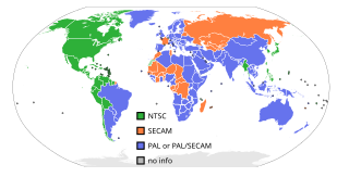
NTSC, named after the National Television System Committee, is the analog television color system that was used in North America from 1954 and until digital conversion, was used in most of the Americas ; Myanmar; South Korea; Taiwan; Philippines; Japan; and some Pacific island nations and territories.
Phase Alternating Line (PAL) is a colour encoding system for analogue television used in broadcast television systems in most countries broadcasting at 625-line / 50 field per second (576i). Other common colour encoding systems are NTSC and SECAM.
In telecommunication, intersymbol interference (ISI) is a form of distortion of a signal in which one symbol interferes with subsequent symbols. This is an unwanted phenomenon as the previous symbols have similar effect as noise, thus making the communication less reliable. The spreading of the pulse beyond its allotted time interval causes it to interfere with neighboring pulses. ISI is usually caused by multipath propagation or the inherent linear or non-linear frequency response of a communication channel causing successive symbols to "blur" together.
A signal generator is an electronic device that generates repeating or non-repeating electronic signals in either the analog or the digital domain. It is generally used in designing, testing, troubleshooting, and repairing electronic or electroacoustic devices, though it often has artistic uses as well.

Pulse width modulation (PWM), or pulse-duration modulation (PDM), is a method of reducing the average power delivered by an electrical signal, by effectively chopping it up into discrete parts. The average value of voltage fed to the load is controlled by turning the switch between supply and load on and off at a fast rate. The longer the switch is on compared to the off periods, the higher the total power supplied to the load. Along with MPPT maximum power point tracking, it is one of the primary methods of reducing the output of solar panels to that which can be utilized by a battery. PWM is particularly suited for running inertial loads such as motors, which are not as easily affected by this discrete switching. Because they have inertia they react slower. The PWM switching frequency has to be high enough not to affect the load, which is to say that the resultant waveform perceived by the load must be as smooth as possible.

A vectorscope is a special type of oscilloscope used in both audio and video applications. Whereas an oscilloscope or waveform monitor normally displays a plot of signal vs. time, a vectorscope displays an X-Y plot of two signals, which can reveal details about the relationship between these two signals. Vectorscopes are highly similar in operation to oscilloscopes operated in X-Y mode; however those used in video applications have specialized graticules, and accept standard television or video signals as input.
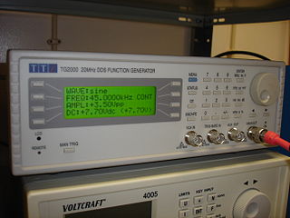
A function generator is usually a piece of electronic test equipment or software used to generate different types of electrical waveforms over a wide range of frequencies. Some of the most common waveforms produced by the function generator are the sine wave, square wave, triangular wave and sawtooth shapes. These waveforms can be either repetitive or single-shot. Integrated circuits used to generate waveforms may also be described as function generator ICs.
Electric power quality, or simply power quality, involves voltage, frequency, and waveform. Good power quality can be defined as a steady supply voltage that stays within the prescribed range, steady a.c. frequency close to the rated value, and smooth voltage curve waveform. In general, it is useful to consider power quality as the compatibility between what comes out of an electric outlet and the load that is plugged into it. The term is used to describe electric power that drives an electrical load and the load's ability to function properly. Without the proper power, an electrical device may malfunction, fail prematurely or not operate at all. There are many ways in which electric power can be of poor quality and many more causes of such poor quality power.
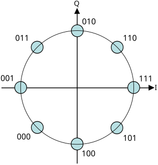
A constellation diagram is a representation of a signal modulated by a digital modulation scheme such as quadrature amplitude modulation or phase-shift keying. It displays the signal as a two-dimensional xy-plane scatter diagram in the complex plane at symbol sampling instants. The angle of a point, measured counterclockwise from the horizontal axis, represents the phase shift of the carrier wave from a reference phase. The distance of a point from the origin represents a measure of the amplitude or power of the signal.
A video signal generator is a type of signal generator which outputs predetermined video and/or television oscillation waveforms, and other signals used in the synchronization of television devices and to stimulate faults in, or aid in parametric measurements of, television and video systems. There are several different types of video signal generators in widespread use. Regardless of the specific type, the output of a video generator will generally contain synchronization signals appropriate for television, including horizontal and vertical sync pulses or sync words. Generators of composite video signals will also include a colorburst signal as part of the output.

A test probe is a physical device used to connect electronic test equipment to a device under test (DUT). Test probes range from very simple, robust devices to complex probes that are sophisticated, expensive, and fragile. Specific types include test prods, oscilloscope probes and current probes. A test probe is often supplied as a test lead, which includes the probe, cable and terminating connector.

An oscilloscope, previously called an oscillograph, and informally known as a scope or o-scope, CRO, or DSO, is a type of electronic test instrument that graphically displays varying signal voltages, usually as a two-dimensional plot of one or more signals as a function of time. Other signals can be converted to voltages and displayed.
This is a subdivision of the Oscilloscope article, discussing the various types and models of oscilloscopes in greater detail.
This article discusses the history and development of oscilloscope technology. The modern day digital oscilloscope grew out of multiple developments of analog oscilloscopes, which in turn grew out of the older oscillograph. The oscillograph started as a hand drawn chart which was later slightly automated. This then grew into galvanometer driven recorders and photographic recorders. Eventually, the cathode ray tube came along and displaced the oscillograph, eventually taking over the majority of the market when advancements such as triggers were added to them. With the lowering costs of digital circuitry, the digital oscilloscope has taken over the majority of the modern oscilloscope sales, with almost no makers offering analog cathode ray tube oscilloscopes. However, the oscillograph lives on to a degree in pen chart recorders for electrical signals.

An Audio Analyzer is a test and measurement instrument used to objectively quantify the audio performance of electronic and electro-acoustical devices. Audio quality metrics cover a wide variety of parameters, including level, gain, noise, harmonic and intermodulation distortion, frequency response, relative phase of signals, interchannel crosstalk, and more. In addition, many manufacturers have requirements for behavior and connectivity of audio devices that require specific tests and confirmations.
This glossary defines terms that are used in the document "Defining Video Quality Requirements: A Guide for Public Safety", developed by the Video Quality in Public Safety (VQIPS) Working Group. It contains terminology and explanations of concepts relevant to the video industry. The purpose of the glossary is to inform the reader of commonly used vocabulary terms in the video domain. This glossary was compiled from various industry sources.
CCIR System A was the 405 line analog broadcast television system broadcast in the UK and Ireland. CCIR service was discontinued in 1985.