Plessey AR-320

Last updated

Plessey AR-320
Country of originUK
Manufacturer Plessey
Introduced1986
No. built6
Type 3D radar, early warning
Frequency S-band
Beamwidth 1.4º horizontal
RPM6 rpm
Range250 nautical miles (460 km; 290 mi)
Azimuth 360º
Power24 kW
Other NamesAMES Type 93
Related BAe Commander

The AR-320 is a 3D early warning radar developed by the UK's Plessey in partnership with US-based ITT-Gilfillan. The system combined the receiver electronics, computer systems and displays of the earlier Plessey AR-3D with a Gilfillan-developed transmitter and planar array antenna from their S320 series. The main advantage over the AR-3D was the ability to shift frequencies to provide a level of frequency agility and thus improve its resistance to jamming.

Contents

The system was designed for sales to the Royal Air Force and a NATO contract for mobile radars on the southern flank of Europe. In 1983, after an extended contest against the Hughes Air Defence Radar, the Royal Air Force ordered six AR-320 systems for their newly forming IUKADGE network under the service name AMES Type 93. The AR-320s were to be held in off-site locations and quickly moved to pre-surveyed areas in case the main radars in the network were attacked. In service, the AR-320 proved to be much less robust than advertised and was ultimately used only in fixed emplacements.

As the radar market grew more demanding and new solid state systems began to replace former vacuum tube systems as high-power microwave sources, the system was extensively redesigned as the AR-325, which, through a series of mergers, became the modern BAe Commander series.

History

Background

During the installation of the first high-power microwave frequency radars using slot antennas, operators of the AMES Type 14 noticed that the apparent angle of the blips on the radar display did not always match the physical angle of the antenna. This was traced to an effect in the waveguides, which had slightly different transmission characteristics based on frequency. When the cavity magnetron warmed and cooled during use, its frequency changed slightly, and a delay was introduced in the waveguide. This caused the signal to no longer exactly match the positioning of the radiators in the antenna, and caused the beam to shift. This effect became known as "squint" and was generally considered annoying, especially on the AMES Type 80 where servicing the magnetron required a lengthy recalibration process to bring the beam back in line with the antenna. [1]

This effect also opened the possibility of steering the beam electronically by deliberately changing the frequency during the period of a long pulse. A magnetron's output is fixed by its physical construction and does not easily allow such shifting. To make practical use of this effect, a much wider bandwidth would be needed, which became possible with the introduction of high-power klystrons and travelling wave tubes in the later 1950s. A number of radar systems began using this technique to provide beam-steering, typically in elevation while the radar spun around its vertical axis to scan in azimuth. [2]

SQUIRT and AR-3D

In 1964, Decca Radar won a contract to study the use of this effect in combination with another emerging technique, pulse compression. In follow-on work they built an experimental system known as SQUIRT which was operational in 1967, the same year Decca's Heavy Radar division was purchased by Plessey. SQUIRT, with modifications made in 1968, demonstrated itself able to scan vertically while providing accurate range measurements, but at the cost of losing accuracy in height finding. [3]

The Ministry of Defence proved uninterested in the result, not only due to the lack of accuracy in altitude but also because a target aircraft would always be "painted" by the same frequency; the vertical angle was a function of frequency, so as long as the aircraft did not change altitude it would always see the same signal. This would make it much easier to jam the radar, making it of limited use in any environment where electronic countermeasures (ECM) was expected. [4] [3]

Plessey felt the concept would still be useful for less demanding roles, notably air traffic control around military bases where the radar would have a secondary early warning role and might not face significant ECM. [3] They developed a commercial model, the Plessey AR-3D, which went on the market in 1975. The system was much less expensive than contemporary systems using phase steering and soon found a number of international sales, with over 20 units eventually being delivered. [4]

S320

Plessey was not the only company to go the route of frequency scanning. In the US, ITT-Gilfillan developed a very similar system in the early 1960s and had used it in a series of radars. In the late 1970s, the company introduced the latest generation of the design, the Series 320, or S320. The major difference in the Gilfillan concept was that several separate receivers were used, each one aimed at a different vertical angle. These were used to extract course altitude rather than using only the frequency as in the AR-3D. [5] This simplified the altitude extraction, although at the cost of having to maintain multiple receivers. [6]

A key feature of the S320 was a programmable signal delay in the transmitter path that allowed the signal to be delayed as it was sent to the antenna. In the AR-3D the elevation angle of the output was a direct function of the frequency, but in the S320, an additional delay could be added to further modify the angle as in the case of a PESA design. This allowed the transmitter to send its pulses at varying base frequencies and then delay the signal so the phase differences re-aligned the output with the antenna boresight. This provided frequency agility in system that still retained much of the simplicity of the frequency scanned system. [6] [5]

Due to the physical construction of the end-fed slot antenna array, the system also exhibited squint in azimuth. The resulting scanning patterns shifted both vertically and horizontally during a pulse, resulting in a diagonal scan. This was corrected by storing the returns pulse-to-pulse in digital form and then shifting them in azimuth in the computer to align them back up. The digital signals were also used for constant false alarm rate (CFAR) bucketing, Doppler analysis, and jamming detection. [5]

AR-320

Shortly after the AR-3D shipped, NATO released a new contract for a mobile radar system for the southern flank. The main features were mobility, ECM resistance, and that it come from a European company. Plessey's AR-3D met two of these criterion, but was not able to meet the ECM requirement. They approached ITT-Gilfillan in the late 1970s and arranged a deal whereby Plessey would license the S320 antenna and transmitter system and then adapt their existing AR-3D receivers and display systems to work with the new frequencies. The result was the AR-320. Likewise, ITT-Gilfillan gained access to Plessey's proven raster-scan display systems, which at that time were still relatively new technology. [6]

Around this time, the Royal Air Force began implementing its new Improved UKADGE radar network, which included the need for a mobile radar that would be stored away from the main radar stations and then set up in a pre-surveyed location in case the main stations were attacked. The AR-320 was an obvious choice for this role as it was precisely how the Marines were using the S320 under the name AN/TPS-32, and an RAF purchase would help potential sales to NATO. [6]

UKADGE was being managed by Hughes Aircraft, who were pushing their own Hughes Air Defense Radar (HADR) for the same role. After months of debate, in 1983 examples of the AR-320 were purchased under the RAF name AMES Type 93. The NATO sale was ultimately lost. The Type 93 systems were delivered in 1986, but by this time IUKADGE had run into significant problems with practically every other part of the overall system. It did not become operational until 1993, by which time the Warsaw Pact had broken up and the need for the mobile backup systems was no longer pressing. [7]

In the field, the AR-320 was found to be difficult to keep operational. This was due to constant parts failure and a lack of spares. Additionally, its reliability after movement was found to be poor. Given the now almost non-existent threat, the Type 93's were removed from their backup role and sent to bases that formerly used older equipment, notably the AN/TPS-77's, which had also proven difficult to maintain. In 1995 there was serious consideration given to removing them from service, but a consortium of the RAF, Siemens Plessey (which had purchased Plessey's radar division by this point) and ITT upgraded the systems and got their performance to a reasonable level. [6]

One of the better-known examples of the Type 93 in service was the unit at RAF Saxa Vord in the Shetland Islands. This unit was earmarked for the site in the late 1980s, and construction of a radome on the base of the former Type 80 radar began in 1988. Over the winter of 1988 the radome was blown over, and then once again on New Year's Day 1991/92. The Type 93 did not begin operations until October 1993 and did not fully replace the earlier systems at the site until April 1995. It operated until April 2006, when the station was closed. The Type 93 was broken up for parts to keep other units operational. [8]

Commander series

In the late 1980s, Plessey began considering upgrades to the array antenna to replace the ITT model, producing a system known as the AR-3DP. This generated some interest in the market and the company arranged several purchase agreements. At the same time, another project began to consider using the AR-3DP antenna with an entirely new transmitter and receiver system as well, which became known as the AR-325. This proved much more interesting, and those agreements for the AR-3DP were re-signed for the AR-325. [9]

As the AR-325 was being developed, in 1989 Siemens purchased the radar division as part of a complex deal that led to the breakup of Plessey and the formation of Siemens Plessey. This company was, in turn, purchased by British Aerospace in 1997. Through this period the system continued to be upgraded as technology changed, leading to the AR-327 Commander in the mid-1990s, known in RAF service as the AMES Type 101, [9] and ultimately to the modern Commander SL, an all solid-state system which bears little in common with the earlier systems. [10]

Description

The S320 antenna consisted of a series of horizontal 5 metres (16 ft)-wide slot antennas stacked on top of each other to form a rectangular planar array. The array was supported from below on a pivot that allowed it to rotate around its vertical axis to provide azimuth scanning. A secondary surveillance radar (SSR) antenna was placed on top, as well as a small omnidirectional antenna used for sidelobe blanking. [6] Some models also had a single feed horn receiver for jamming evaluation. The main array assembly could be folded across a horizontal hinge point roughly 23 up the main antenna, with the top folded back towards the base to form an A-shape that could be secured for transport. [11]

The signal was created in a liquid-cooled two-stage amplifier which sent its output to the antenna via a waveguide. To keep the signal in-phase as it moved up the array, the waveguide was a "serpentine" design, a series of 90 degree bends that passed the signal by the array elements in alternating directions. A series of phase delays in the serpentine handled the shifting needed to properly align the signals with the output slots depending on the base frequency. [6]

Due to the curvature of the Earth, aircraft at long range appear at lower angles. To improve detection range, the signal uses a non-linear frequency ramping, spending more time at lower frequencies and thus lower angles. This produces longer, and thus stronger, returns from targets at low angles. These primary detection pulses were interspersed with dedicated moving-target indication (MTI) pulses which were purely linear. The MTI pulses were used to measure fixed objects like hills or slow-moving objects like wind-blown rain, and did not require the same sort of range performance. [6]

On reception, the signal was sent into an intermediate frequency (IF) system that down-converted the signal to 500 MHz, and then sent the result into a series of five separate additional IF receivers, each turned to a different base frequency and thus a different vertical angle. The output from these receivers had pulse compression applied using surface acoustic wave delays to improve range resolution and was then digitized using analog-to-digital converters. The resulting digital data was then "de-squinted", adjusting its apparent location to remove any frequency-related shift, and then fed into the target detection system. Additionally, the MTI system was aided by further adjusting the phase delay of the lowest angle of the antenna to cancel out any net movement in the clutter, like rain. [6]

Much of the system's resistance to ECM was accomplished in the constant false alarm rate processing. [6] CFAR algorithms are used to extract signals from noisy input by looking for pulses that have higher energy than the overall noise rate. Most jammers produce what appears to be short pulses of signal spread across a wide bandwidth. Because the radar broadcasts across a wide spectrum, jammers also have to spread their signal out across the entire bandwidth. On reception, however, only a much smaller bandwidth is accepted into any one receiver, thereby reducing the amount of jammer signal received. By averaging the power of the returned signal in a single receiver, the target return can be more cleanly picked out on the majority of pulses.

Jammers also confuse the radar image by sending out signals that are strong enough to be picked up in the antenna side lobes, producing false returns that appear in other directions. Planar arrays naturally have low sidelobes, typically on the order of 25 dB down from the main signal, which helps reduce this problem. The AR-320 further reduced this input through the use of an omnidirectional antenna that received all signals so their timing could be established. This allowed the processor to determine which returns were being received in the sidelobes instead of the main beam. [6]

The receiver side of the system contained a separate built-in test equipment (BITE) processor to monitor the system. The transmitter side did not, and this was considered a significant problem. A separate system also allowed simulations to be run that featured both targets as well as ECM. [6]

Related Research Articles

<span class="mw-page-title-main">Radar</span> Object detection system using radio waves

Radar is a radiolocation system that uses radio waves to determine the distance (ranging), angle (azimuth), and radial velocity of objects relative to the site. It is used to detect and track aircraft, ships, spacecraft, guided missiles, motor vehicles, map weather formations, and terrain. A radar system consists of a transmitter producing electromagnetic waves in the radio or microwaves domain, a transmitting antenna, a receiving antenna and a receiver and processor to determine properties of the objects. Radio waves from the transmitter reflect off the objects and return to the receiver, giving information about the objects' locations and speeds.

<span class="mw-page-title-main">Phased array</span> Array of antennas creating a steerable beam

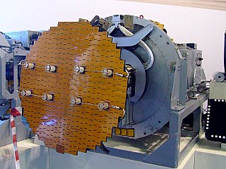
In antenna theory, a phased array usually means an electronically scanned array, a computer-controlled array of antennas which creates a beam of radio waves that can be electronically steered to point in different directions without moving the antennas. The general theory of an electromagnetic phased array also finds applications in ultrasonic and medical imaging application and in optics optical phased array.

<span class="mw-page-title-main">Active electronically scanned array</span> Type of phased array radar

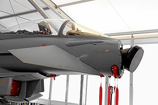
An active electronically scanned array (AESA) is a type of phased array antenna, which is a computer-controlled antenna array in which the beam of radio waves can be electronically steered to point in different directions without moving the antenna. In the AESA, each antenna element is connected to a small solid-state transmit/receive module (TRM) under the control of a computer, which performs the functions of a transmitter and/or receiver for the antenna. This contrasts with a passive electronically scanned array (PESA), in which all the antenna elements are connected to a single transmitter and/or receiver through phase shifters under the control of the computer. AESA's main use is in radar, and these are known as active phased array radar (APAR).

<span class="mw-page-title-main">Pulse-Doppler radar</span> Type of radar system

A pulse-Doppler radar is a radar system that determines the range to a target using pulse-timing techniques, and uses the Doppler effect of the returned signal to determine the target object's velocity. It combines the features of pulse radars and continuous-wave radars, which were formerly separate due to the complexity of the electronics.

Electronic counter-countermeasures (ECCM) is a part of electronic warfare which includes a variety of practices which attempt to reduce or eliminate the effect of electronic countermeasures (ECM) on electronic sensors aboard vehicles, ships and aircraft and weapons such as missiles. ECCM is also known as electronic protective measures (EPM), chiefly in Europe. In practice, EPM often means resistance to jamming. A more detailed description defines it as the electronic warfare operations taken by a radar to offset the enemy's countermeasure.

A low-probability-of-intercept radar (LPIR) is a radar employing measures to avoid detection by passive radar detection equipment while it is searching for a target or engaged in target tracking. This characteristic is desirable in a radar because it allows finding and tracking an opponent without alerting them to the radar's presence. This also protects the radar installation from anti-radiation missiles (ARMs).

<span class="mw-page-title-main">AN/APG-68</span> Radar system

The AN/APG-68 radar is a long range Pulse-doppler radar designed by Westinghouse to replace AN/APG-66 radar in the F-16 Fighting Falcon. The AN/APG-68(V)8 and earlier radar system consists of the following line-replaceable units:

Monopulse radar is a radar system that uses additional encoding of the radio signal to provide accurate directional information. The name refers to its ability to extract range and direction from a single signal pulse.

<span class="mw-page-title-main">Passive electronically scanned array</span> Type of antenna

A passive electronically scanned array (PESA), also known as passive phased array, is an antenna in which the beam of radio waves can be electronically steered to point in different directions, in which all the antenna elements are connected to a single transmitter and/or receiver. The largest use of phased arrays is in radars. Most phased array radars in the world are PESA. The civilian microwave landing system uses PESA transmit-only arrays.

<span class="mw-page-title-main">AN/SPS-48</span>

The AN/SPS-48 is a US naval electronically scanned array, air search three-dimensional radar system manufactured by ITT Exelis and deployed in the 1960s as the primary air search sensor for anti-aircraft warships. The deployment of the AN/SPY-1 and the end of the Cold War led to the decommissioning of many such ships, and many of these vessel's AN/SPS-48 sets were reused on aircraft carriers and amphibious ships where it is used to direct targets for air defense systems such as the Sea Sparrow and RIM-116 SAM missiles. Existing sets are being modernized under the ROAR program to AN/SPS-48G standard for better reliability and usability.

<span class="mw-page-title-main">Radar display</span> Electronic device

A radar display is an electronic device that presents radar data to the operator. The radar system transmits pulses or continuous waves of electromagnetic radiation, a small portion of which backscatter off targets and return to the radar system. The receiver converts all received electromagnetic radiation into a continuous electronic analog signal of varying voltage that can be converted then to a screen display.

A radar system uses a radio-frequency electromagnetic signal reflected from a target to determine information about that target. In any radar system, the signal transmitted and received will exhibit many of the characteristics described below.

<span class="mw-page-title-main">RCA AN/FPS-16 Instrumentation Radar</span> Ground radar

The AN/FPS-16 is a highly accurate ground-based monopulse single object tracking radar (SOTR), used extensively by the NASA crewed space program, the U.S. Air Force and the U.S. Army. The accuracy of Radar Set AN/FPS-16 is such that the position data obtained from point-source targets has azimuth and elevation angular errors of less than 0.1 milliradian and range errors of less than 5 yards (5 m) with a signal-to-noise ratio of 20 decibels or greater.

Radar engineering details are technical details pertaining to the components of a radar and their ability to detect the return energy from moving scatterers — determining an object's position or obstruction in the environment. This includes field of view in terms of solid angle and maximum unambiguous range and velocity, as well as angular, range and velocity resolution. Radar sensors are classified by application, architecture, radar mode, platform, and propagation window.

Frequency agility is the ability of a radar system to quickly shift its operating frequency to account for atmospheric effects, jamming, mutual interference with friendly sources, or to make it more difficult to locate the radar broadcaster through radio direction finding. The term can also be applied to other fields, including lasers or traditional radio transceivers using frequency-division multiplexing, but it remains most closely associated with the radar field and these other roles generally use the more generic term "frequency hopping".

<span class="mw-page-title-main">AMES Type 82</span> Cold War-era British medium-range 3D radar

The AMES Type 82, also widely known by its rainbow codename Orange Yeoman, was an S-band 3D radar built by the Marconi Company and used by the Royal Air Force (RAF), initially for tactical control and later for air traffic control (ATC).

<span class="mw-page-title-main">RX12874</span> Military radar detector

RX12874, also known as the Passive Detection System (PDS) and by its nickname "Winkle", was a radar detector system used as part of the Royal Air Force's Linesman/Mediator radar network until the early 1980s. Winkle passed out of service along with the rest of the Linesman system as the IUKADGE network replaced it.

<span class="mw-page-title-main">AMES Type 85</span> Cold War-era British early warning radar

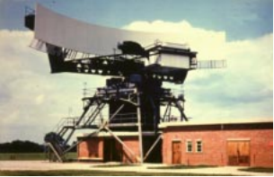
The AMES Type 85, also known by its rainbow code Blue Yeoman, was an extremely powerful early warning (EW) and fighter direction (GCI) radar used by the Royal Air Force (RAF) as part of the Linesman/Mediator radar network. First proposed in early 1958, it was eleven years before they became operational in late 1968, by which time they were already considered obsolete. The Type 85 remained the RAF's primary air defense radar until it was replaced by Marconi Martello sets in the late-1980s as part of the new IUKADGE network.

Martello is a family of phased array radar systems developed by Marconi Electronic Systems in the 1970s and introduced operationally in the early 1980s. They provided long-range early warning capabilities but also had the accuracy needed for interception plotting and "putting on" of other weapons systems like surface-to-air missiles. The name comes from the Martello towers that provided defence in earlier years.

The AR-3D was a military air traffic control and early warning radar developed by Plessey and first produced in 1975. It used a pencil beam and simple frequency scanning system known as "squint scan" to produce a low-cost 3D radar system that was also relatively mobile. About 23 were produced in total and found sales around the world into the early 1980s.

References

Citations

  1. Gough 1993, pp. 320–321.
  2. Gough 1993, p. 320.
  3. 1 2 3 Gough 1993, p. 321.
  4. 1 2 Burr 2010, p. 7.5.
  5. 1 2 3 Pfister 1980, p. 628.
  6. 1 2 3 4 5 6 7 8 9 10 11 12 Burr 2010, p. 7.6.
  7. IUKADGE (PDF) (Technical report). Forecast International. April 1997. p. 6.
  8. Carle, Gordon (9 September 2011). "Type 93".
  9. 1 2 Burr 2010, p. 7.7.
  10. Burr 2010, p. 7.8.
  11. Carle, Gordon (10 May 2010). "Departure of the Type 93 radar". p. see images.

Bibliography