Plessey AR-3D

Last updated

Plessey AR-3D
Country of originUK
Manufacturer Plessey
Introduced1975
No. built23
Type 3D radar, early warning
Frequency S-band, 2915 to 3055 MHz
PRF 250 pps
Beamwidth  horizontal
 vertical
Pulsewidth36 μS
RPM6 rpm
Range260 nautical miles (480 km; 300 mi)
Diameter12 by 12 metres (39 by 39 ft)
Azimuth 360º
Precision40 m range, 0.16º azimuth
Power1.1 MW
Other NamesAMES Type 94

The AR-3D was a military air traffic control and early warning radar developed by Plessey and first produced in 1975. It used a pencil beam and simple frequency scanning system known as "squint scan" to produce a low-cost 3D radar system that was also relatively mobile. About 23 were produced in total and found sales around the world into the early 1980s.

Contents

The frequency scanning system had the disadvantage that a target aircraft would always be "painted" by the same frequency signal, which made the task of jamming the radar simpler. This limited its sales prospects to military users, and shortly after delivering the AR-3D the company began negotiations with the US company ITT-Gillifan to incorporate their multi-frequency scanning with the AR-3D's receivers and display systems to produce the Plessey AR-320.

History

Squint

During the installation of the first high-power microwave frequency radars using slot antennas, operators of the AMES Type 14 noticed that the apparent angle of the "blips" on the radar display did not always match the physical angle of the antenna. This was traced to an effect in the waveguides, which had slightly different transmission characteristics based on frequency. When the cavity magnetron warmed and cooled during use, its frequency changed slightly, and a delay was introduced in the waveguide. This caused the signal to no longer exactly match the positioning of the radiators in the antenna, and caused the beam to shift. This effect became known as "squint" and was generally considered annoying, especially on the AMES Type 80 where servicing the magnetron required a lengthy recalibration process to bring the beam back in line with the antenna. [1]

Through the 1960s, significant effort was put into developing "squintless feeds" that avoided this problem, but the problem also presented an opportunity. Squint is caused by the waveguide system slowing the signal by different amounts depending on the frequency. If the signal exits through a slotted waveguide antenna, this slight shift in timing produces a phase shift of the output. This shift will cause the resulting wavefront to change direction. This is the basis of the phased array radar, which normally accomplishes this using signal delay electronics. As squint causes a similar delay, it can also be used to steer the beam. This leads to the possibility of radar that can scan its beam in a chosen direction, typically vertically, with no moving parts. [2]

SQUIRT

Another technique that was being widely explored in the late 1950s and early 1960s was the technique of pulse compression. Pulse compression greatly increases the range resolution of a radar, which was formerly defined almost entirely by its pulse width. To get the required resolution in older designs, pulses were very short, typically a few microseconds, which required massive power output in order to produce a detectable reflected signal. Using pulse compression, the pulses could be much longer, at least ten times, meaning the same return signal would be produced with 110 the peak output. [3]

Pulse compression works by changing the frequency of the signal over the time of the pulse and then delaying the returned signal based on its frequency. This compresses the return into a short pulse that can then be used for accurate ranging. This presented a potential issue in a radar using squint scanning, which would presumably send the signals in different directions if pulse compression were used. It appeared that as long as the beam steering was at the right speed it would be possible to do both; a given target would only see a small change in frequency as the beam scanned passed it, but the signal would dwell on any one target long enough that there would be a notable frequency shift during the resulting reflection that could be used for pulse compression. [3]

In 1964, Plessey won a contract to consider the issue and began development of an experimental system. This was completed in 1967 as SQUIRT. Early tests demonstrated the system worked in theory, but the returned signal was weak and the system did not have the desired detection range. The system was modified and testing resumed in 1968 with the result that the detection range had improved but the height finding accuracy was lower than desired. It was finally concluded that the difference in the performance of the system across the 10 MHz bandwidth was too great to be practical. [3]

AR-3D

Plessey felt the basic concept still offered significant benefits, at least in less-demanding roles, and that it could be greatly improved by increasing the bandwidth past what was possible with its original 1960s-era systems. In 1973 they received Ministry of Defence (MoD) funding to build an example set with a potential 150 MHz bandwidth, which was operational the next year. [3] In 1975, [4] the company put it on the market as the AR-3D, offered for military air traffic control (ATC) and "limited air defense purposes". [3] The ideal market would be day-to-day traffic control around a military airport, where the secondary function of early warning would still be useful. [4] It was displayed publicly at the Paris Air Show in 1975. [5] At the time, they predicted sales of up to 50 systems worldwide. [6]

The system as a whole consisted of the antenna and its mount, six short semi-trailers of equipment, and one full-length semi-trailer with the operations room. It was airmobile via Chinook helicopter. Sales followed with Egypt taking three units, South Africa ten, and Qatar and Ecuador two each. The RAF used one in Germany for ATC around RAF Gatow and sent two to the Falkland Islands in January 1983 followed by another in February 1984. [4] According to Burr, the countries were assigned code names, with Penguin referring to the UK Ministry of Defence, and Rodent, Condor, Lion and Falcon to outside-UK sales. This list shows a total of 23 examples being produced. [7] Those used by the RAF were given the name AMES Type 94. [8]

Newspaper reports from 1986 state another six were sold to Iran, but it is not clear if this is included in the list above or represents new-build systems. Given the late date of the sale, this may be systems "recycled" from RAF use or other sales. [9]

AR-320

Although successful in the market, the AR-3D had the significant disadvantage in the military role in that a particular target would always be "painted" by the same frequency signal, and thus jamming the signal would be greatly simplified. [6] Most other 3D radars of the era did not use squint scanning and thus did not suffer from this problem. Seeking a way to apply their work on the AR-3D to a new frequency agile radar, Plessey entered an agreement with ITT-Gilfillan of Los Angeles. Gilfillan also used squint scanning, but did so at different frequencies with each pulse, and thus avoided the problems with the AR-3D. Gilfillan supplied a new antenna and transmitters, while Plessey supplied suitably modified versions of the existing receiver and display systems. The result was the Plessey AR-320, which replaced the AR-3D in the market. [4]

Description

The system was packaged as a complete unit known as the Type 40/80-5 Command and Control Post. This consisted of the antenna unit on a four-legged mounting, a Transmitter Cabin, two Diesel Generators, Communications Cabin, Workshop Cabin and the Processing and Control Cabin. Most of these were in the form of short semi-trailers, although the Processing and Control Cabin was full-length. Although designed primarily to be pulled by prime movers, the system was also airmobile via Chinook helicopter. [4]

The antenna rotated around its vertical axis to scan in azimuth. The reflector took the form of a vertical cylindrical paraboloid, with the lower corners cropped off. The end-fed slot feed antenna was held in front of the reflector by three sets of legs forming triangular supports, one at the top and two at the bottom, the lowest also feeding the signal. The antenna was mounted at one end of its support platform, seemingly unbalanced, while the Transmitter Cabin was positioned at the other where it connected to a waveguide running along the top of the platform. [4]

The transmitter used two stages, the first being a travelling wave tube and the second a grid klystron. Total peak power was 1.1 MW while average power was 10 kW. The transmitter had a bandwidth of 140 MHz during its 36 microseconds pulses. [4]

On reception, the signal was converted to an intermediate frequency and then split into eight signal paths, each of which accepted a range of frequencies in order to perform coarse vertical angle determination. Pulse compression was then added using an acoustic surface wave filter, compressing it to 100 nanoseconds. The lowest elevation "beams" also had moving target indication clutter suppression to eliminate ground returns. [4]

The output of the receivers was then sent to a plot extractor, which identified moving objects in the returns and attempted to automatically assign tracking information - direction and speed. The result was then sent to the multiple displays in the Processing and Control Cabin. The data could also be sent over datalink via the Communications Cabin. [4]

Related Research Articles

Microwave Electromagnetic radiation with wavelengths from 1 m to 1 mm

Microwave is a form of electromagnetic radiation with wavelengths ranging from about one meter to one millimeter corresponding to frequencies between 300 MHz and 300 GHz respectively. Different sources define different frequency ranges as microwaves; the above broad definition includes both UHF and EHF bands. A more common definition in radio-frequency engineering is the range between 1 and 100 GHz. In all cases, microwaves include the entire SHF band at minimum. Frequencies in the microwave range are often referred to by their IEEE radar band designations: S, C, X, Ku, K, or Ka band, or by similar NATO or EU designations.

Radar Object detection system using radio waves

Radar is a detection system that uses radio waves to determine the distance (ranging), angle, and radial velocity of objects relative to the site. It can be used to detect aircraft, ships, spacecraft, guided missiles, motor vehicles, weather formations, and terrain. A radar system consists of a transmitter producing electromagnetic waves in the radio or microwaves domain, a transmitting antenna, a receiving antenna and a receiver and processor to determine properties of the object(s). Radio waves from the transmitter reflect off the object and return to the receiver, giving information about the object's location and speed.

Active electronically scanned array Type of phased array radar

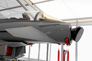
An active electronically scanned array (AESA) is a type of phased array antenna, which is a computer-controlled array antenna in which the beam of radio waves can be electronically steered to point in different directions without moving the antenna. In the AESA, each antenna element is connected to a small solid-state transmit/receive module (TRM) under the control of a computer, which performs the functions of a transmitter and/or receiver for the antenna. This contrasts with a passive electronically scanned array (PESA), in which all the antenna elements are connected to a single transmitter and/or receiver through phase shifters under the control of the computer. AESA's main use is in radar, and these are known as active phased array radar (APAR).

Pulse-Doppler radar

A pulse-Doppler radar is a radar system that determines the range to a target using pulse-timing techniques, and uses the Doppler effect of the returned signal to determine the target object's velocity. It combines the features of pulse radars and continuous-wave radars, which were formerly separate due to the complexity of the electronics.

A low-probability-of-intercept radar (LPIR) is a radar employing measures to avoid detection by passive radar detection equipment while it is searching for a target or engaged in target tracking. This characteristic is desirable in a radar because it allows finding and tracking an opponent without alerting them to the radar's presence. This also protects the radar installation from anti-radiation missiles (ARM).

Squint (antenna)

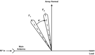
In a phased array or slotted waveguide antenna, squint refers to the angle that the transmission is offset from the normal of the plane of the antenna. In simple terms, it is the change in the beam direction as a function of operating frequency, polarization, or orientation. It is an important phenomenon that can limit the bandwidth in phased array antenna systems.

AN/FPS-117

The AN/FPS-117 is an L-band active electronically scanned array (AESA) 3-dimensional air search radar first produced by GE Aerospace in 1980 and now part of Lockheed Martin. The system offers instrumented detection at ranges on the order of 200 to 250 nautical miles and has a wide variety of interference and clutter rejection systems.

Linesman/Mediator was a dual-purpose civil and military radar network in the United Kingdom between the 1960s and 1984. The military side (Linesman) was replaced by the Improved United Kingdom Air Defence Ground Environment (IUKADGE), while the civilian side (Mediator) became the modern public-private National Air Traffic Services (NATS).

Monopulse radar is a radar system that uses additional encoding of the radio signal to provide accurate directional information. The name refers to its ability to extract range and direction from a single signal pulse.
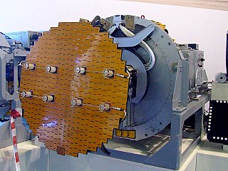
A radar system uses a radio-frequency electromagnetic signal reflected from a target to determine information about that target. In any radar system, the signal transmitted and received will exhibit many of the characteristics described below.

Radar engineering details are technical details pertaining to the components of a radar and their ability to detect the return energy from moving scatterers — determining an object's position or obstruction in the environment. This includes field of view in terms of solid angle and maximum unambiguous range and velocity, as well as angular, range and velocity resolution. Radar sensors are classified by application, architecture, radar mode, platform, and propagation window.

Type 277 radar

The Type 277 was a surface search and secondary aircraft early warning radar used by the Royal Navy and allies during World War II and the post-war era. It was a major update of the earlier Type 271 radar, offering much more power, better signal processing, new displays, and new antennas with greatly improved performance and much simpler mounting requirements. It allowed a radar with performance formerly found only on cruisers and battleships to be fitted even to the smallest corvettes. It began to replace the 271 in 1943 and was widespread by the end of the year.

AMES Type 82

The AMES Type 82, also widely known by its rainbow codename Orange Yeoman, was an S-band 3D radar built by Marconi and used by the Royal Air Force (RAF), initially for tactical control and later for air traffic control (ATC).

RX12874

RX12874, also known as the Passive Detection System (PDS) and by its nickname "Winkle", was a radar detector system used as part of the Royal Air Force's Linesman/Mediator radar network until the early 1980s. Winkle passed out of service along with the rest of the Linesman system as the IUKADGE network replaced it.

AMES Type 80

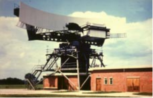
The AMES Type 80, sometimes known by its development rainbow code Green Garlic, was a powerful early warning (EW) and ground-controlled interception (GCI) radar developed by the Telecommunications Research Establishment (TRE) and built by Decca for the Royal Air Force (RAF). It could reliably detect a large fighter or small bomber at ranges over 210 nautical miles, and large, high-flying aircraft were seen out to the radar horizon. It was the primary military ground-based radar in the UK from the mid-1950s into the late 1960s, providing coverage over the entire British Isles.

AMES Type 85

The AMES Type 85, also known by its rainbow code Blue Yeoman, was an extremely powerful early warning (EW) and fighter direction (GCI) radar used by the Royal Air Force (RAF) as part of the Linesman/Mediator radar network. First proposed in early 1958, it was eleven years before they became operational in late 1968, by which time they were already considered obsolete. The Type 85 remained the RAF's primary air defense radar until it was replaced by Marconi Martello sets in the late-1980s as part of the new IUKADGE network.

The AMES Type 84, also known as the Microwave Early Warning or MEW, was a 23 cm wavelength early warning radar used by the Royal Air Force (RAF) as part of the Linesman/Mediator radar network. Operating in the L-band gave it improved performance in rain and hail, where the primary AMES Type 85 radar's performance dropped off. It operated beside the Type 85 and RX12874 in Linesman, and moved to the UKADGE system in the 1980s before being replaced during UKADGE upgrades in the early 1990s.

Martello is a family of phased array radar systems developed by Marconi Electronic Systems in the 1970s and introduced operationally in the early 1980s. They provided long-range early warning capabilities but also had the accuracy needed for interception plotting and "putting on" of other weapons systems like surface-to-air missiles. The name comes from the Martello towers that provided defence in earlier years.

The HF200 is a height finder radar designed and first built by Decca Radar in 1957, and continuing sales into the 1970s after the division was purchased by Plessey in 1965. It was one of the company's successful heavy radar projects, winning the contract for many of the ROTOR stations in the UK and additional sales around the world with a total production run of about 40 examples. These served into the 1980s, and in one case, 1993, before 3D radars removed the need for separate height-finders.

The AR-320 is a 3D early warning radar developed by the UK's Plessey in partnership with US-based ITT-Gilfillan. The system combined the receiver electronics, computer systems and displays of the earlier Plessey AR-3D with a Gilfillan-developed transmitter and planar array antenna from their S320 series. The main advantage over the AR-3D was the ability to shift frequencies to provide a level of frequency agility and thus improve its resistance to jamming.

References

Citations

  1. Gough 1993, pp. 320–321.
  2. Gough 1993, p. 320.
  3. 1 2 3 4 5 Gough 1993, p. 321.
  4. 1 2 3 4 5 6 7 8 9 Burr 2010, p. Chapter 7.
  5. "Exhibitors at the Paris Air Show". Aircraft Engineering and Aerospace Technology: 48. 1 May 1975.
  6. 1 2 New 1974, p. 26.
  7. Burr 2010, p. Appendix 3.
  8. "AR-320".
  9. "Paper Says Britain Granted Licence For Radar System For Iran". AP News. 11 December 1986.

Bibliography