Prism coupler

Last updated

A prism coupler is a prism designed to couple a substantial fraction of the power contained in a beam of light (e.g., a laser beam) into a thin film to be used as a waveguide without the need for precision polishing of the edge of the film, without the need for sub-micrometer alignment precision of the beam and the edge of the film, and without the need for matching the numerical aperture of the beam to the film. Using a prism coupler, a beam coupled into a thin film can have a diameter hundreds of times the thickness of the film. Invention of the coupler contributed to the initiation of a field of study known as integrated optics.

Contents

History

The theory underlying the prism coupler was first published in the Soviet Union. [1] This work was not known in the US. Starting in 1969, Shubert, Harris, and Polky at the University of Washington, [2] [3] [4] and, independently, Tien, Ulrich, and Martin, at Bell Laboratories [5] [6] [7] described the first experiments with prism coupling and its underlying theory. This was done with a view toward device applications of thin films. [8] [9]

Configuration

Prism coupler with incident beam. Prism Coupler with incident beam.png
Prism coupler with incident beam.

A prism coupler is used to couple the power from an incident laser beam into a thin film. The film lies on a substrate such as a glass microscope slide and might have a thickness of the order of the wavelength of the incident light (0.550 μm for green light). The refractive index of the film is made greater than that of the glass slide, the film can serve as a dielectric planar waveguide for light via total internal reflection off the film–glass interface (and film–air interface). The prism coupler consists of a near cube of high–refractive-index glass and a second thin film at the bottom that contacts the waveguide film and serves the function of partially containing the guided wave over the coupling distance. The thin film at the bottom of the prism is referred to as the tunneling layer. The tunneling layer must have a lower refractive index than the waveguide film and may actually be implemented as a layer of air. The thickness of the tunneling layer will be on the order of a fraction of a wavelength (tens to hundreds of nanometers for visible light).

The prism and tunneling layer are pressed against the waveguide film. The beam enters the front face of the prism and strikes the tunneling layer somewhat more than half a beam width away from the face opposite the entry face of the prism. The ranking of refractive indices of the four regions of the combined coupler and waveguide structure must be as follows: the refractive index of the glass slide and the tunneling layer must be lowest, next is the refractive index of the guide film, and highest is the index of the prism.

Prism coupler with light scattered from a guided wave, and reflection from the bottom of the substrate. File-Prism Coupler with light scattered from a guided wave, and reflection from the bottom of the substrate.png
Prism coupler with light scattered from a guided wave, and reflection from the bottom of the substrate.
Two prism couplers with output beam (right) transferred via a guided wave and. incident and reflected beams (left). Two Prism Couplers with output beam .png
Two prism couplers with output beam (right) transferred via a guided wave and. incident and reflected beams (left).

Theory

A prism coupler may be explained in terms of the reciprocity theorem. The reciprocity theorem permits the relative power coupled into the thin film by an incident beam to be computed from the solution to a reciprocal problem. In the reciprocal problem, a waveguide mode in the film (travelling to the left in the first figure) is incident on the prism coupler. Barring significant scattering at the prism interface, the waveguide mode in the reciprocal problem retains its form as a mode and propagates under the prism, losing power as it propagates due to radiation into the prism. The power in the prism emerges as a collimated beam at an angle determined by the propagation constant of the waveguide mode and the refractive index of the prism. Radiation into the prism occurs because the evanescent tail of the waveguide mode touches the bottom of the prism. The waveguide mode tunnels through the tunneling layer.

Efficient coupling of light into the film occurs when the incident beam (arriving from the left shown in the first figure), evaluated at the bottom face of the prism, has the same shape as the radiated beam in the reciprocal problem. When the power in both the incident beam and the reciprocal waveguide mode is normalized, the fractional coupling amplitude is expressed as an integral over the product of the incident wave and the radiated reciprocal field. The integral is a surface integral taken over the bottom face of the prism. From such an integral we deduce three key features:

  1. To couple in a significant fraction of the incident power, the incident beam must arrive at the angle that renders it phase matched to the waveguide mode.
  2. The transverse behavior of the waveguide mode launched in the film (transverse to the direction of propagation) will be essentially that of the incident beam.
  3. If the thickness of the tunneling layer is adjusted appropriately, it is possible, in principle, to couple nearly all the light in the beam into the waveguide film.

Suppressing the transverse part of the representation for the fields, and taking x as direction to the left in Fig. 1, the waveguide mode in the reciprocal problem takes the monotonically decreasing form

where α(x) is the attenuation rate and is the propagation constant of the waveguide mode.

The associated transverse field at the bottom of the prism takes the form

with A a normalization constant.

The transverse field of the incident beam will have the form

where f(x) is a normalized Gaussian, or other beam form, and βin is the longitudinal component of the propagation constant of the incident beam.

When βin = βw, integration of

yields the coupling amplitude. Adjusting α(x) permits the coupling to approach unity, barring significant geometry-dependent diffractive effects.

Remarks

The Goos-Hänchen shift describes the displacement of the center point of an optical beam when it undergoes total reflection from the interface between two semi-infinite regions of different refractive index. The displacement is generally of the order of the wavelength of light. If the reflection of a beam from a sandwich structure that consists of a semi-infinite prism, a tunneling layer, a waveguide film layer, and a semi-infinite glass slide is investigated, the shift will be found to be much larger as a consequence of the excitation of the guided wave. Terminating the upper (prism) region just beyond the midpoint of the incident beam traps the light of the beam in the waveguide mode in the film.

Excitation of the guided wave by an incident beam can also be viewed as a problem in coupled modes, the modes being the waveguide mode and a representation for the incident beam. Power introduced into one branch of a coupled mode structure can transfer to the other branch along the structure.

Measurement applications

Prism couplers are instruments used to measure the refractive index/birefringence and thickness of dielectric and polymer films. Since refractive indices of a material depend upon the wavelength of the electromagnetic radiation transmitted, a monochromatic laser is used in conjunction with a prism of known refractive index. The laser beam is directed through a side of the prism, bent, and is normally reflected back out the opposite side into a photo detector. However, at certain values of the incident angle theta, the beam does not reflect back out, but instead is transmitted through the base into the film sample. These angles are called "mode angles". A computer-driven rotary table varies the incident angle of the laser. The first mode angle found determines the refractive index, and the angle difference from one mode to the next determines the sample thickness.

Prism couplers also allow for coupling light in and out of a waveguide without exposing the cross-section of the waveguide (edge coupling). The general condition for coupling from free-space is

where is the index of air (~1) and is the propagation constant of the waveguide. In order to have a guided mode, . This would imply that , which is not possible, and hence, this is why a prism is needed to achieved the phase matching condition. A phase matching condition is required between the propagation constant of the mth mode in the waveguide and the incident light at an angle normal from the waveguide surface.

where is the index of refraction of the prism. [10]


Related Research Articles

<span class="mw-page-title-main">Refractive index</span> Ratio of the speed of light in vacuum to that in the medium

In optics, the refractive index of an optical medium is a dimensionless number that gives the indication of the light bending ability of that medium.

In electrodynamics, elliptical polarization is the polarization of electromagnetic radiation such that the tip of the electric field vector describes an ellipse in any fixed plane intersecting, and normal to, the direction of propagation. An elliptically polarized wave may be resolved into two linearly polarized waves in phase quadrature, with their polarization planes at right angles to each other. Since the electric field can rotate clockwise or counterclockwise as it propagates, elliptically polarized waves exhibit chirality.

In electromagnetics, an evanescent field, or evanescent wave, is an oscillating electric and/or magnetic field that does not propagate as an electromagnetic wave but whose energy is spatially concentrated in the vicinity of the source. Even when there is a propagating electromagnetic wave produced, one can still identify as an evanescent field the component of the electric or magnetic field that cannot be attributed to the propagating wave observed at a distance of many wavelengths.

<span class="mw-page-title-main">Prism (optics)</span> Transparent optical element with flat, polished surfaces that refract light

An optical prism is a transparent optical element with flat, polished surfaces that are designed to refract light. At least one surface must be angled — elements with two parallel surfaces are not prisms. The most familiar type of optical prism is the triangular prism, which has a triangular base and rectangular sides. Not all optical prisms are geometric prisms, and not all geometric prisms would count as an optical prism. Prisms can be made from any material that is transparent to the wavelengths for which they are designed. Typical materials include glass, acrylic and fluorite.

A transverse mode of electromagnetic radiation is a particular electromagnetic field pattern of the radiation in the plane perpendicular to the radiation's propagation direction. Transverse modes occur in radio waves and microwaves confined to a waveguide, and also in light waves in an optical fiber and in a laser's optical resonator.

<span class="mw-page-title-main">Optical ring resonators</span>

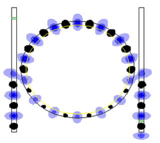
An optical ring resonator is a set of waveguides in which at least one is a closed loop coupled to some sort of light input and output. The concepts behind optical ring resonators are the same as those behind whispering galleries except that they use light and obey the properties behind constructive interference and total internal reflection. When light of the resonant wavelength is passed through the loop from the input waveguide, the light builds up in intensity over multiple round-trips owing to constructive interference and is output to the output bus waveguide which serves as a detector waveguide. Because only a select few wavelengths will be at resonance within the loop, the optical ring resonator functions as a filter. Additionally, as implied earlier, two or more ring waveguides can be coupled to each other to form an add/drop optical filter.

An optical waveguide is a physical structure that guides electromagnetic waves in the optical spectrum. Common types of optical waveguides include optical fiber waveguides, transparent dielectric waveguides made of plastic and glass, liquid light guides, and liquid waveguides.

<span class="mw-page-title-main">Double-clad fiber</span>

Double-clad fiber (DCF) is a class of optical fiber with a structure consisting of three layers of optical material instead of the usual two. The inner-most layer is called the core. It is surrounded by the inner cladding, which is surrounded by the outer cladding. The three layers are made of materials with different refractive indices.

<span class="mw-page-title-main">Dispersive prism</span> Device used to disperse light

In optics, a dispersive prism is an optical prism that is used to disperse light, that is, to separate light into its spectral components. Different wavelengths (colors) of light will be deflected by the prism at different angles. This is a result of the prism material's index of refraction varying with wavelength (dispersion). Generally, longer wavelengths (red) undergo a smaller deviation than shorter wavelengths (blue). The dispersion of white light into colors by a prism led Sir Isaac Newton to conclude that white light consisted of a mixture of different colors.

<span class="mw-page-title-main">Acousto-optics</span> The study of sound and light interaction

Acousto-optics is a branch of physics that studies the interactions between sound waves and light waves, especially the diffraction of laser light by ultrasound through an ultrasonic grating.

<span class="mw-page-title-main">Transfer-matrix method (optics)</span>

The transfer-matrix method is a method used in optics and acoustics to analyze the propagation of electromagnetic or acoustic waves through a stratified medium; a stack of thin films. This is, for example, relevant for the design of anti-reflective coatings and dielectric mirrors.

Eigenmode expansion (EME) is a computational electrodynamics modelling technique. It is also referred to as the mode matching technique or the bidirectional eigenmode propagation method. Eigenmode expansion is a linear frequency-domain method.

<span class="mw-page-title-main">Thin-film interference</span> Optical phenomenon

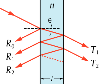
Thin-film interference is a natural phenomenon in which light waves reflected by the upper and lower boundaries of a thin film interfere with one another, increasing reflection at some wavelengths and decreasing it at others. When white light is incident on a thin film, this effect produces colorful reflections.

Leaky-wave antenna (LWA) belong to the more general class of traveling wave antenna, that use a traveling wave on a guiding structure as the main radiating mechanism. Traveling-wave antenna fall into two general categories, slow-wave antennas and fast-wave antennas, which are usually referred to as leaky-wave antennas.

Holographic optical element (HOE) is an optical component (mirror, lens, directional diffuser, etc.) that produces holographic images using principles of diffraction. HOE is most commonly used in transparent displays, 3D imaging, and certain scanning technologies. The shape and structure of the HOE is dependent on the piece of hardware it is needed for, and the coupled wave theory is a common tool used to calculate the diffraction efficiency or grating volume that helps with the design of an HOE. Early concepts of the holographic optical element can be traced back to the mid-1900s, coinciding closely with the start of holography coined by Dennis Gabor. The application of 3D visualization and displays is ultimately the end goal of the HOE; however, the cost and complexity of the device has hindered the rapid development toward full 3D visualization. The HOE is also used in the development of augmented reality(AR) by companies such as Google with Google Glass or in research universities that look to utilize HOEs to create 3D imaging without the use of eye-wear or head-wear. Furthermore, the ability of the HOE to allow for transparent displays have caught the attention of the US military in its development of better head-up displays (HUD) which is used to display crucial information for aircraft pilots.

Marcatili’s method is an approximate analytical method that describes how light propagates through rectangular dielectric optical waveguides. It was published by Enrique Marcatili in 1969.

Surface plasmon resonance microscopy (SPRM), also called surface plasmon resonance imaging (SPRI), is a label free analytical tool that combines the surface plasmon resonance of metallic surfaces with imaging of the metallic surface. The heterogeneity of the refractive index of the metallic surface imparts high contrast images, caused by the shift in the resonance angle. SPRM can achieve a sub-nanometer thickness sensitivity and lateral resolution achieves values of micrometer scale. SPRM is used to characterize surfaces such as self-assembled monolayers, multilayer films, metal nanoparticles, oligonucleotide arrays, and binding and reduction reactions. Surface plasmon polaritons are surface electromagnetic waves coupled to oscillating free electrons of a metallic surface that propagate along a metal/dielectric interface. Since polaritons are highly sensitive to small changes in the refractive index of the metallic material, it can be used as a biosensing tool that does not require labeling. SPRM measurements can be made in real-time, such as measuring binding kinetics of membrane proteins in single cells, or DNA hybridization.

An Edge Emitting LED (ELED) fulfills the requirement of high brightness LED, which provides high-efficiency coupling to optical fibers.

The operation of a photon scanning tunneling microscope (PSTM) is analogous to the operation of an electron scanning tunneling microscope, with the primary distinction being that PSTM involves tunneling of photons instead of electrons from the sample surface to the probe tip. A beam of light is focused on a prism at an angle greater than the critical angle of the refractive medium in order to induce total internal reflection within the prism. Although the beam of light is not propagated through the surface of the refractive prism under total internal reflection, an evanescent field of light is still present at the surface.

Optical holography is a technique which enables an optical wavefront to be recorded and later re-constructed. Holography is best known as a method of generating three-dimensional images but it also has a wide range of other applications.

References

  1. L.V. Iogansen, "Theory of resonant electromagnetic systems with total internal reflection III," Sov. Phys. Tech. Phys., vol. 11, pp. 1529–1534, May 1967.
  2. J.H. Harris and R. Shubert, "Optimum power transfer from a beam to a surface wave," Conf. Abs., URSI Spr. Mtg, p. 71, Wash. D.C. April, 1969.
  3. J.H. Harris, R. Shubert, and J.N. Polky, "Beam Coupling to Films," J.Opt.Soc.Am., v.60, pp. 1007–1016, Aug. 1970
  4. J.H. Harris and R. Shubert, "Variable Tunneling Excitation of Optical Surface Waves," IEEE Trans. MTT, pp. 74–91, Mar.1971
  5. P.K.Tien, R.Ulrich, and R.L.Martin, "Modes of propagating light waves in thin deposited semiconductor films," Appl. Phys. Letters, 14, p291 May, 1969
  6. P.K. Tien and R. Ulrich, "Theory of prism-film coupler and thin film light guides," J. Opt. Soc. Am. V.60, pp. 1325–1337 Oct. 1970
  7. R. Ulrich, "Theory of the prism-film coupler by plane wave analysis," J. Opt. Soc. Am. V.60, pp. 1337–1350 Oct. 1970
  8. R. Shubert and J.H. Harris, "Optical Surface Waves on Thin films and their Application to Integrated Data Processors," IEEE Trans. MTT, pp. 1048–1054, v. MTT-16 Dec.1968
  9. S.E. Miller, "Integrated optics: an introduction," Bell Syst. Tech. J., V.48, pp. 2059–2069, Sept. 1969
  10. R. Hunsperger. Integrated Optics. Springer. 1995.