Synchronization (alternating current)

Last updated

In an alternating current (AC) electric power system, synchronization is the process of matching the frequency and phase and voltage of a generator or other source to an electrical grid in order to transfer power. If two unconnected segments of a grid are to be connected to each other, they cannot safely exchange AC power until they are synchronized.

Contents

A direct current (DC) generator can be connected to a power network simply by adjusting its open-circuit terminal voltage to match the network's voltage, by either adjusting its speed or its field excitation. The exact engine speed is not critical. However, an AC generator must additionally match its timing (frequency and phase) to the network voltage, which requires both speed and excitation to be systematically controlled for synchronization. This extra complexity was one of the arguments against AC operation during the war of currents in the 1880s. In modern grids, synchronization of generators is carried out by automatic systems.

Conditions

There are five conditions that must be met before the synchronization process takes place. The source (generator or sub-network) must have equal root-mean-square voltage, frequency, phase sequence, phase angle, and waveform to that of the system to which it is being synchronized. [1]

Waveform and phase sequence are fixed by the construction of the generator and its connections to the system. During installation of a generator, careful checks are made to ensure the generator terminals and all control wiring is correct so that the order of phases (phase sequence) matches the system. Connecting a generator with the wrong phase sequence will result in large, possibly damaging, currents as the system voltages are opposite to those of the generator terminal voltages. [2]

The voltage, frequency and phase angle must be controlled each time a generator is to be connected to a grid. [1]

Generating units for connection to a power grid have an inherent droop speed control that allows them to share load proportional to their rating. Some generator units, especially in isolated systems, operate with isochronous frequency control, maintaining constant system frequency independent of load.

Process

The sequence of events is similar for manual or automatic synchronization. The generator is brought up to approximate synchronous speed by supplying more energy to its shaft - for example, opening the valves on a steam turbine, opening the gates on a hydraulic turbine, or increasing the fuel rack setting on a diesel engine. The field of the generator is energized and the voltage at the terminals of the generator is observed and compared with the system. The voltage magnitude must be the same as the system voltage.

If one machine is slightly out of phase it will pull into step with the others but, if the phase difference is large, there will be heavy cross-currents which can cause voltage fluctuations and, in extreme cases, damage to the machines.

From top to bottom: synchroscope, voltmeter, frequency meter. When the two systems are synchronized, the pointer on the synchrosope is stationary and points straight up. Synchronoscope stack.jpg
From top to bottom: synchroscope, voltmeter, frequency meter. When the two systems are synchronized, the pointer on the synchrosope is stationary and points straight up.

Synchronizing lamps

Formerly, three incandescent light bulbs were connected between the generator terminals and the system terminals (or more generally, to the terminals of instrument transformers connected to generator and system). As the generator speed changes, the lights will flicker at the beat frequency proportional to the difference between generator frequency and system frequency. When the voltage at the generator is opposite to the system voltage (either ahead or behind in phase), the lamps will be bright. When the voltage at the generator matches the system voltage, the lights will be dark. At that instant, the circuit breaker connecting the generator to the system may be closed and the generator will then stay in synchronism with the system. [3]

An alternative technique used a similar scheme to the above except that the connections of two of the lamps were swapped either at the generator terminals or the system terminals. In this scheme, when the generator was in synchronism with the system, one lamp would be dark, but the two with the swapped connections would be of equal brightness. Synchronizing on "dark" lamps was preferred over "bright" lamps because it was easier to discern the minimum brightness. However, a lamp burnout could give a false-positive for successful synchronization.

Synchroscope

This synchroscope was used to synchronize a factory's power plant with the utility's power grid. Synchroscope.jpg
This synchroscope was used to synchronize a factory's power plant with the utility's power grid.

Another manual method of synchronization relies on observing an instrument called a "synchroscope", which displays the relative frequencies of system and generator. The pointer of the synchroscope will indicate "fast" or "slow" speed of the generator with respect to the system. To minimize the transient current when the generator circuit breaker is closed, usual practice is to initiate the close as the needle slowly approaches the in-phase point. An error of a few electrical degrees between system and generator will result in a momentary inrush and abrupt speed change of the generator.

Synchronizing relays

Synchronizing relays allow unattended synchronization of a machine with a system. Today these are digital microprocessor instruments, but in the past electromechanical relay systems were applied. A synchronizing relay is useful to remove human reaction time from the process, or when a human is not available such as at a remote controlled generating plant. Synchroscopes or lamps are sometimes installed as a supplement to automatic relays, for possible manual use or for monitoring the generating unit.

Sometimes as a precaution against out-of-step connection of a machine to a system, a "synchro check" relay is installed that prevents closing the generator circuit breaker unless the machine is within a few electrical degrees of being in-phase with the system. Synchro check relays are also applied in places where several sources of supply may be connected and where it is important that out-of-step sources are not accidentally paralleled.

Synchronous operation

While the generator is synchronized, the frequency of the system will change depending on load and the average characteristics of all the generating units connected to the grid. [1] Large changes in system frequency can cause the generator to fall out of synchronism with the system. Protective devices on the generator will operate to disconnect it automatically.

Synchronous speeds

Synchronous speeds for synchronous motors and alternators depend on the number of poles on the machine and the frequency of the supply.

The relationship between the supply frequency, f, the number of poles, p, and the synchronous speed (speed of rotating field), ns is given by:

.

In the following table, frequencies are shown in hertz (Hz) and rotational speeds in revolutions per minute (rpm):

No. of polesSpeed (rpm) at 50 HzSpeed (rpm) at 60 Hz
23,0003,600
41,5001,800
61,0001,200
8750900
10600720
12500600
14429514
16375450
18333400
20300360
22273327
24250300
26231277
28214257
30200240

See also

Related Research Articles

<span class="mw-page-title-main">Electric generator</span> Device that converts other energy to electrical energy

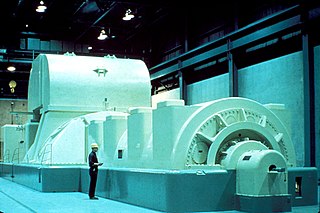
In electricity generation, a generator is a device that converts motive power or fuel-based power into electric power for use in an external circuit. Sources of mechanical energy include steam turbines, gas turbines, water turbines, internal combustion engines, wind turbines and even hand cranks. The first electromagnetic generator, the Faraday disk, was invented in 1831 by British scientist Michael Faraday. Generators provide nearly all of the power for electric power grids.

<span class="mw-page-title-main">Alternator</span> Device converting mechanical into electrical energy

An alternator is an electrical generator that converts mechanical energy to electrical energy in the form of alternating current. For reasons of cost and simplicity, most alternators use a rotating magnetic field with a stationary armature. Occasionally, a linear alternator or a rotating armature with a stationary magnetic field is used. In principle, any AC electrical generator can be called an alternator, but usually the term refers to small rotating machines driven by automotive and other internal combustion engines.

<span class="mw-page-title-main">Power inverter</span> Device that changes direct current (DC) to alternating current (AC)

A power inverter, inverter or invertor is a power electronic device or circuitry that changes direct current (DC) to alternating current (AC). The resulting AC frequency obtained depends on the particular device employed. Inverters do the opposite of rectifiers which were originally large electromechanical devices converting AC to DC.

<span class="mw-page-title-main">Synchronous motor</span> Type of AC motor

A synchronous electric motor is an AC electric motor in which, at steady state, the rotation of the shaft is synchronized with the frequency of the supply current; the rotation period is exactly equal to an integral number of AC cycles. Synchronous motors contain multiphase AC electromagnets on the stator of the motor that create a magnetic field which rotates in time with the oscillations of the line current. The rotor with permanent magnets or electromagnets turns in step with the stator field at the same rate and as a result, provides the second synchronized rotating magnet field of any AC motor. A synchronous motor is termed doubly fed if it is supplied with independently excited multiphase AC electromagnets on both the rotor and stator.

<span class="mw-page-title-main">Utility frequency</span> Frequency used on standard electricity grid in a given area

The utility frequency, (power) line frequency or mains frequency is the nominal frequency of the oscillations of alternating current (AC) in a wide area synchronous grid transmitted from a power station to the end-user. In large parts of the world this is 50 Hz, although in the Americas and parts of Asia it is typically 60 Hz. Current usage by country or region is given in the list of mains electricity by country.

A motor controller is a device or group of devices that can coordinate in a predetermined manner the performance of an electric motor. A motor controller might include a manual or automatic means for starting and stopping the motor, selecting forward or reverse rotation, selecting and regulating the speed, regulating or limiting the torque, and protecting against overloads and electrical faults. Motor controllers may use electromechanical switching, or may use power electronics devices to regulate the speed and direction of a motor.

<span class="mw-page-title-main">15 kV AC railway electrification</span> Standard current and voltage settings for much of Central Europes train transport

Railway electrification using alternating current (AC) at 15 kilovolts (kV) and 16.7 hertz (Hz) are used on transport railways in Germany, Austria, Switzerland, Sweden, and Norway. The high voltage enables high power transmission with the lower frequency reducing the losses of the traction motors that were available at the beginning of the 20th century. Railway electrification in late 20th century tends to use 25 kV, 50 Hz AC systems which has become the preferred standard for new railway electrifications but extensions of the existing 15 kV networks are not completely unlikely. In particular, the Gotthard Base Tunnel still uses 15 kV, 16.7 Hz electrification.

This is an alphabetical list of articles pertaining specifically to electrical and electronics engineering. For a thematic list, please see List of electrical engineering topics. For a broad overview of engineering, see List of engineering topics. For biographies, see List of engineers.

<span class="mw-page-title-main">Synchroscope</span>

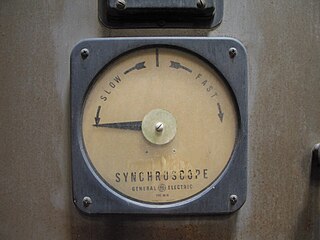
In AC electrical power systems, a synchroscope is a device that indicates the degree to which two systems are synchronized with each other.

Power system protection is a branch of electrical power engineering that deals with the protection of electrical power systems from faults through the disconnection of faulted parts from the rest of the electrical network. The objective of a protection scheme is to keep the power system stable by isolating only the components that are under fault, whilst leaving as much of the network as possible in operation. The devices that are used to protect the power systems from faults are called protection devices.

<span class="mw-page-title-main">AC motor</span> Electric motor driven by an AC electrical input

An AC motor is an electric motor driven by an alternating current (AC). The AC motor commonly consists of two basic parts, an outside stator having coils supplied with alternating current to produce a rotating magnetic field, and an inside rotor attached to the output shaft producing a second rotating magnetic field. The rotor magnetic field may be produced by permanent magnets, reluctance saliency, or DC or AC electrical windings.

In the design of electrical power systems, the ANSI standard device numbers identifies the features of a protective device such as a relay or circuit breaker. These types of devices protect electrical systems and components from damage when an unwanted event occurs, such as an electrical fault. Device numbers are used to identify the functions of devices shown on a schematic diagram. Function descriptions are given in the standard.

Islanding is the condition in which a distributed generator (DG) continues to power a location even though external electrical grid power is no longer present. Islanding can be dangerous to utility workers, who may not realize that a circuit is still powered, and it may prevent automatic re-connection of devices. Additionally, without strict frequency control, the balance between load and generation in the islanded circuit can be violated, thereby leading to abnormal frequencies and voltages. For those reasons, distributed generators must detect islanding and immediately disconnect from the circuit; this is referred to as anti-islanding.

Doubly-fed electric machines also slip-ring generators are electric motors or electric generators, where both the field magnet windings and armature windings are separately connected to equipment outside the machine.

An induction generator or asynchronous generator is a type of alternating current (AC) electrical generator that uses the principles of induction motors to produce electric power. Induction generators operate by mechanically turning their rotors faster than synchronous speed. A regular AC induction motor usually can be used as a generator, without any internal modifications. Because they can recover energy with relatively simple controls, induction generators are useful in applications such as mini hydro power plants, wind turbines, or in reducing high-pressure gas streams to lower pressure.

<span class="mw-page-title-main">Electric power system</span> Network of electrical component deployed to generate, transmit & distribute electricity

An electric power system is a network of electrical components deployed to supply, transfer, and use electric power. An example of a power system is the electrical grid that provides power to homes and industries within an extended area. The electrical grid can be broadly divided into the generators that supply the power, the transmission system that carries the power from the generating centers to the load centers, and the distribution system that feeds the power to nearby homes and industries.

<span class="mw-page-title-main">Electrical grid</span> Interconnected network for delivering electricity from suppliers to consumers

An electrical grid is an interconnected network for electricity delivery from producers to consumers. Electrical grids vary in size and can cover whole countries or continents. It consists of:

<span class="mw-page-title-main">Wide area synchronous grid</span> Regional electrical grid

A wide area synchronous grid is a three-phase electric power grid that has regional scale or greater that operates at a synchronized utility frequency and is electrically tied together during normal system conditions. Also known as synchronous zones, the most powerful is the Northern Chinese State Grid with 1,700 gigawatts (GW) of generation capacity, while the widest region served is that of the IPS/UPS system serving most countries of the former Soviet Union. Synchronous grids with ample capacity facilitate electricity trading across wide areas. In the ENTSO-E in 2008, over 350,000 megawatt hours were sold per day on the European Energy Exchange (EEX).

This glossary of electrical and electronics engineering is a list of definitions of terms and concepts related specifically to electrical engineering and electronics engineering. For terms related to engineering in general, see Glossary of engineering.

<span class="mw-page-title-main">Synchronverter</span> Type of electrical power inverter

Synchronverters or virtual synchronous generators are inverters which mimic synchronous generators (SG) to provide "synthetic inertia" for ancillary services in electric power systems. Inertia is a property of standard synchronous generators associated with the rotating physical mass of the system spinning at a frequency proportional to the electricity being generated. Inertia has implications towards grid stability as work is required to alter the kinetic energy of the spinning physical mass and therefore opposes changes in grid frequency. Inverter-based generation inherently lacks this property as the waveform is being created artificially via power electronics.

References

  1. 1 2 3 Soft synchronization of dispersed generators to micro grids for smart grid applications
  2. Terrell Croft and Wilford Summers (ed), American Electricans' Handbook, Eleventh Edition, McGraw Hill, New York (1987) ISBN   0-07-013932-6 pages 7-45 through 7-49
  3. Donald G. Fink and H. Wayne Beaty, Standard Handbook for Electrical Engineers, Eleventh Edition, McGraw-Hill, New York, 1978, ISBN   0-07-020974-X pp. 3-64,3-65

Sources