This article needs additional citations for verification .(September 2014) |
- This page is about waveguides for acoustics and sound, for other types of waveguide, see Waveguide
An acoustic waveguide is a physical structure for guiding sound waves.
This article needs additional citations for verification .(September 2014) |
An acoustic waveguide is a physical structure for guiding sound waves.
One example might be a speaking tube used aboard ships for communication between decks. Other examples include the rear passage in a transmission line loudspeaker enclosure, the ear canal or a device like a stethoscope. The term also applies to guided waves in solids.
A duct for sound propagation also behaves like a transmission line (e.g. air conditioning duct, car muffler, etc.). [1] [2] The duct contains some medium, such as air, that supports sound propagation. Its length is typically around a quarter of the wavelength which is intended to be guided, but the dimensions of its cross section are smaller than this. Sound is introduced at one end of the tube by forcing the pressure to vary in the direction of propagation, which causes a pressure gradient to travel perpendicular to the cross section at the speed of sound. When the wave reaches the end of the transmission line, its behaviour depends on what is present at the end of the line. There are three generalized scenarios:
A low impedance load (e.g. leaving the end open in free air) will cause a reflected wave in which the sign of the pressure variation reverses, but the direction of the pressure wave remains the same.
A load that matches the characteristic impedance (defined below) will completely absorb the wave and the energy associated with it. No reflection will occur.
A high impedance load (e.g. by plugging the end of the line) will cause a reflected wave in which the direction of the pressure wave is reversed but the sign of the pressure remains the same.
Since a transmission line behaves like a four terminal model, one cannot really define or measure the impedance of a transmission line component. One can however measure its input or output impedance. It depends on the cross-sectional area and length of the line, the sound frequency, as well as the characteristic impedance of the sound propagating medium within the duct. Only in the exceptional case of a closed end tube (to be compared with electrical short circuit), the input impedance could be regarded as a component impedance.
Where a transmission line of finite length is mismatched at both ends, there is the potential for a wave to bounce back and forth many times until it is absorbed. This phenomenon is a kind of resonance and will tend to attenuate any signal fed into the line.
When this resonance effect is combined with some sort of active feedback mechanism and power input, it is possible to set up an oscillation which can be used to generate periodic acoustic signals such as musical notes (e.g. in an organ pipe).
The application of transmission line theory is however seldom used in acoustics. An equivalent four terminal model which splits the downstream and upstream waves is used. This eases the introduction of physically measurable acoustic characteristics, reflection coefficients, material constants of insulation material, the influence of air velocity on wavelength (Mach number), etc. This approach also circumvents impractical theoretical concepts, such as acoustic impedance of a tube, which is not measurable because of its inherent interaction with the sound source and the load of the acoustic component.

In electrical engineering, a transmission line is a specialized cable or other structure designed to conduct electromagnetic waves in a contained manner. The term applies when the conductors are long enough that the wave nature of the transmission must be taken into account. This applies especially to radio-frequency engineering because the short wavelengths mean that wave phenomena arise over very short distances. However, the theory of transmission lines was historically developed to explain phenomena on very long telegraph lines, especially submarine telegraph cables.

A waveguide is a structure that guides waves, such as electromagnetic waves or sound, with minimal loss of energy by restricting the transmission of energy to one direction. Without the physical constraint of a waveguide, wave intensities decrease according to the inverse square law as they expand into three-dimensional space.

A loudspeaker is an electroacoustic transducer that converts an electrical audio signal into a corresponding sound. A speaker system, also often simply referred to as a "speaker" or "loudspeaker", comprises one or more such speaker drivers, an enclosure, and electrical connections possibly including a crossover network. The speaker driver can be viewed as a linear motor attached to a diaphragm which couples that motor's movement to motion of air, that is, sound. An audio signal, typically from a microphone, recording, or radio broadcast, is amplified electronically to a power level capable of driving that motor in order to reproduce the sound corresponding to the original unamplified electronic signal. This is thus the opposite function to the microphone; indeed the dynamic speaker driver, by far the most common type, is a linear motor in the same basic configuration as the dynamic microphone which uses such a motor in reverse, as a generator.

In radio engineering, an antenna or aerial is the interface between radio waves propagating through space and electric currents moving in metal conductors, used with a transmitter or receiver. In transmission, a radio transmitter supplies an electric current to the antenna's terminals, and the antenna radiates the energy from the current as electromagnetic waves. In reception, an antenna intercepts some of the power of a radio wave in order to produce an electric current at its terminals, that is applied to a receiver to be amplified. Antennas are essential components of all radio equipment.

In electronics, impedance matching is the practice of designing or adjusting the input impedance or output impedance of an electrical device for a desired value. Often, the desired value is selected to maximize power transfer or minimize signal reflection. For example, impedance matching typically is used to improve power transfer from a radio transmitter via the interconnecting transmission line to the antenna. Signals on a transmission line will be transmitted without reflections if the transmission line is terminated with a matching impedance.
A resonator is a device or system that exhibits resonance or resonant behavior. That is, it naturally oscillates with greater amplitude at some frequencies, called resonant frequencies, than at other frequencies. The oscillations in a resonator can be either electromagnetic or mechanical. Resonators are used to either generate waves of specific frequencies or to select specific frequencies from a signal. Musical instruments use acoustic resonators that produce sound waves of specific tones. Another example is quartz crystals used in electronic devices such as radio transmitters and quartz watches to produce oscillations of very precise frequency.

A horn loudspeaker is a loudspeaker or loudspeaker element which uses an acoustic horn to increase the overall efficiency of the driving element(s). A common form (right) consists of a compression driver which produces sound waves with a small metal diaphragm vibrated by an electromagnet, attached to a horn, a flaring duct to conduct the sound waves to the open air. Another type is a woofer driver mounted in a loudspeaker enclosure which is divided by internal partitions to form a zigzag flaring duct which functions as a horn; this type is called a folded horn speaker. The horn serves to improve the coupling efficiency between the speaker driver and the air. The horn can be thought of as an "acoustic transformer" that provides impedance matching between the relatively dense diaphragm material and the less-dense air. The result is greater acoustic output power from a given driver.
In microwave and radio-frequency engineering, a stub or resonant stub is a length of transmission line or waveguide that is connected at one end only. The free end of the stub is either left open-circuit, or short-circuited. Neglecting transmission line losses, the input impedance of the stub is purely reactive; either capacitive or inductive, depending on the electrical length of the stub, and on whether it is open or short circuit. Stubs may thus function as capacitors, inductors and resonant circuits at radio frequencies.

Acoustic resonance is a phenomenon in which an acoustic system amplifies sound waves whose frequency matches one of its own natural frequencies of vibration.

In radio-frequency engineering and communications engineering, waveguide is a hollow metal pipe used to carry radio waves. This type of waveguide is used as a transmission line mostly at microwave frequencies, for such purposes as connecting microwave transmitters and receivers to their antennas, in equipment such as microwave ovens, radar sets, satellite communications, and microwave radio links.
A loudspeaker enclosure or loudspeaker cabinet is an enclosure in which speaker drivers and associated electronic hardware, such as crossover circuits and, in some cases, power amplifiers, are mounted. Enclosures may range in design from simple, homemade DIY rectangular particleboard boxes to very complex, expensive computer-designed hi-fi cabinets that incorporate composite materials, internal baffles, horns, bass reflex ports and acoustic insulation. Loudspeaker enclosures range in size from small "bookshelf" speaker cabinets with 4-inch (10 cm) woofers and small tweeters designed for listening to music with a hi-fi system in a private home to huge, heavy subwoofer enclosures with multiple 18-inch (46 cm) or even 21-inch (53 cm) speakers in huge enclosures which are designed for use in stadium concert sound reinforcement systems for rock music concerts.

An acoustic transmission line is the use of a long duct, which acts as an acoustic waveguide and is used to produce or transmit sound in an undistorted manner. Technically it is the acoustic analog of the electrical transmission line, typically conceived as a rigid-walled duct or tube, that is long and thin relative to the wavelength of sound present in it.

Underwater acoustics or hydroacoustics is the study of the propagation of sound in water and the interaction of the mechanical waves that constitute sound with the water, its contents and its boundaries. The water may be in the ocean, a lake, a river or a tank. Typical frequencies associated with underwater acoustics are between 10 Hz and 1 MHz. The propagation of sound in the ocean at frequencies lower than 10 Hz is usually not possible without penetrating deep into the seabed, whereas frequencies above 1 MHz are rarely used because they are absorbed very quickly.

In physics, sound is a vibration that propagates as an acoustic wave, through a transmission medium such as a gas, liquid or solid. In human physiology and psychology, sound is the reception of such waves and their perception by the brain. Only acoustic waves that have frequencies lying between about 20 Hz and 20 kHz, the audio frequency range, elicit an auditory percept in humans. In air at atmospheric pressure, these represent sound waves with wavelengths of 17 meters (56 ft) to 1.7 centimeters (0.67 in). Sound waves above 20 kHz are known as ultrasound and are not audible to humans. Sound waves below 20 Hz are known as infrasound. Different animal species have varying hearing ranges.
A quarter-wave impedance transformer, often written as λ/4 impedance transformer, is a transmission line or waveguide used in electrical engineering of length one-quarter wavelength (λ), terminated with some known impedance. It presents at its input the dual of the impedance with which it is terminated.
Nominal impedance in electrical engineering and audio engineering refers to the approximate designed impedance of an electrical circuit or device. The term is applied in a number of different fields, most often being encountered in respect of:

A waveguide filter is an electronic filter constructed with waveguide technology. Waveguides are hollow metal conduits inside which an electromagnetic wave may be transmitted. Filters are devices used to allow signals at some frequencies to pass, while others are rejected. Filters are a basic component of electronic engineering designs and have numerous applications. These include selection of signals and limitation of noise. Waveguide filters are most useful in the microwave band of frequencies, where they are a convenient size and have low loss. Examples of microwave filter use are found in satellite communications, telephone networks, and television broadcasting.

Planar transmission lines are transmission lines with conductors, or in some cases dielectric (insulating) strips, that are flat, ribbon-shaped lines. They are used to interconnect components on printed circuits and integrated circuits working at microwave frequencies because the planar type fits in well with the manufacturing methods for these components. Transmission lines are more than simply interconnections. With simple interconnections, the propagation of the electromagnetic wave along the wire is fast enough to be considered instantaneous, and the voltages at each end of the wire can be considered identical. If the wire is longer than a large fraction of a wavelength, these assumptions are no longer true and transmission line theory must be used instead. With transmission lines, the geometry of the line is precisely controlled so that its electrical behaviour is highly predictable. At lower frequencies, these considerations are only necessary for the cables connecting different pieces of equipment, but at microwave frequencies the distance at which transmission line theory becomes necessary is measured in millimetres. Hence, transmission lines are needed within circuits.
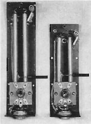
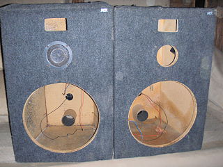
A transmission line loudspeaker is a loudspeaker enclosure design which uses the topology of an acoustic transmission line within the cabinet, compared to the simpler enclosures used by sealed (closed) or ported designs. Instead of reverberating in a fairly simple damped enclosure, sound from the back of the bass speaker is directed into a long damped pathway within the speaker enclosure, which allows far greater control and use of speaker energy and the resulting sound.
Transmission loss (TL) in duct acoustics describes the acoustic performances of a muffler-like system. It is frequently used in the industry areas such as muffler manufacturers and NVH department of automobile manufacturers, and in academic studies. Generally the higher transmission loss of a system it has, the better it will perform in terms of noise cancellation.