Circuit design

Last updated

The process of circuit design can cover systems ranging from complex electronic systems down to the individual transistors within an integrated circuit. One person can often do the design process without needing a planned or structured design process for simple circuits. Still, teams of designers following a systematic approach with intelligently guided computer simulation are becoming increasingly common for more complex designs. In integrated circuit design automation, the term "circuit design" often refers to the step of the design cycle which outputs the schematics of the integrated circuit. Typically this is the step between logic design and physical design. [1]

Contents

Process

A circuit diagram for the Texas Instruments SN76477 sound chip 76477 Musical Organ.JPG
A circuit diagram for the Texas Instruments SN76477 sound chip

Traditional circuit design usually involves several stages. Sometimes, a design specification is written after liaising with the customer. A technical proposal may be written to meet the requirements of the customer specification. The next stage involves synthesising on paper a schematic circuit diagram, an abstract electrical or electronic circuit that will meet the specifications. A calculation of the component values to meet the operating specifications under specified conditions should be made. Simulations may be performed to verify the correctness of the design.

A breadboard or other prototype version of the design for testing against specification may be built. It may involve making any alterations to the circuit to achieve compliance. A choice as to a method of construction and all the parts and materials to be used must be made. There is a presentation of component and layout information to draughtspersons and layout and mechanical engineers for prototype production. This is followed by the testing or type-testing several prototypes to ensure compliance with customer requirements. Usually, there is a signing and approval of the final manufacturing drawings, and there may be post-design services (obsolescence of components, etc.).

Specification

Microchips Mikroel 0141 lille4.jpg
Microchips

The process of circuit design begins with the specification, which states the functionality that the finished design must provide but does not indicate how it is to be achieved . [2] The initial specification is a technically detailed description of what the customer wants the finished circuit to achieve and can include a variety of electrical requirements, such as what signals the circuit will receive, what signals it must output, what power supplies are available and how much power it is permitted to consume. The specification can (and normally does) also set some of the physical parameters that the design must meet, such as size, weight, moisture resistance, temperature range, thermal output, vibration tolerance, and acceleration tolerance. [3]

As the design process progresses, the designer(s) will frequently return to the specification and alter it to take account of the progress of the design. This can involve tightening specifications that the customer has supplied and adding tests that the circuit must pass to be accepted. These additional specifications will often be used in the verification of a design. Changes that conflict with or modify the customer's original specifications will almost always have to be approved by the customer before they can be acted upon.

Correctly identifying the customer needs can avoid a condition known as 'design creep', which occurs in the absence of realistic initial expectations, and later by failing to communicate fully with the client during the design process. It can be defined in terms of its results; "at one extreme is a circuit with more functionality than necessary, and at the other is a circuit having an incorrect functionality". [4] [ who? ] Nevertheless, some changes can be expected. It is good practice to keep options open for as long as possible because it's easier to remove spare elements from the circuit later on than it is to put them in.

Design

A block diagram of 4-bit ALU ALU Block Diagram.png
A block diagram of 4-bit ALU

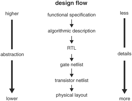
The design process involves moving from the specification at the start to a plan that contains all the information needed to be physically constructed at the end; this happens typically by passing through several stages, although in the straightforward circuit, it may be done in a single step. [5] The process usually begins with the conversion of the specification into a block diagram of the various functions that the circuit must perform, at this stage the contents of each block are not considered, only what each block must do, this is sometimes referred to as a "black box" design. This approach allows the possibly highly complex task to be broken into smaller tasks either by tackled in sequence or divided amongst members of a design team.

Each block is then considered in more detail, still at an abstract stage, but with a lot more focus on the details of the electrical functions to be provided. At this or later stages, it is common to require a large amount of research or mathematical modeling into what is and is not feasible to achieve. [6] The results of this research may be fed back into earlier stages of the design process, for example if it turns out one of the blocks cannot be designed within the parameters set for it, it may be necessary to alter other blocks instead. At this point, it is also common to start considering both how to demonstrate that the design does meet the specifications, and how it is to be tested ( which can include self diagnostic tools ). [7]

Individual circuit components Componentes electronicos.jpg
Individual circuit components

Finally, the individual circuit components are chosen to carry out each function in the overall design; at this stage, the physical layout and electrical connections of each component are also decided, this layout commonly taking the form of artwork for the production of a printed circuit board or Integrated circuit. This stage is typically highly time-consuming because of the vast array of choices available. A practical constraint on the design at this stage is standardization;. At the same time, a certain value of a component may be calculated for use in some location in a circuit; if that value cannot be purchased from a supplier, then the problem has still not been solved. To avoid this, a certain amount of 'catalog engineering' can be applied to solve the more mundane tasks within an overall design.

One area of rapid technology development is in the field of nanoelectronic circuit design. [8]

Costs

Comparison chart between field-effect transistors. Comparison between field-effect transistors en.svg
Comparison chart between field-effect transistors.

Generally, the cost of designing circuits is directly tied to the final circuits' complexity. The greater the complexity (quantity of components and design novelty), the more hours of a skilled engineer's time will be necessary to create a functional product. The process can be tedious, as minute details or features could take any amount of time, materials and manpower to create. Like taking into account the effects of modifying transistor sizes or codecs. [9] In the world of flexible electronics, replacing the, widely used, polyimide substrates with materials like PEN or PET to produce flexible electronics, could reduce costs by factors of 5-10. [10]

Costs for designing a circuit are almost always far higher than production costs per unit, as the cost of production and function of the circuit depends greatly on the design of the circuit. [11]

Although the typical PCB production methods involve subtractive manufacturing, there are methods that use an additive manufacturing process, such as using a 3D printer to "print" a PCB. This method is thought to cost less than additive manufacturing and eliminates the need for waste management altogether. [12]

A graph of the growing number of transistors on circuits each year, otherwise known as Moore's Law Moore's Law Transistor Count 1970-2020.png
A graph of the growing number of transistors on circuits each year, otherwise known as Moore's Law

Verification and testing

Once a circuit has been designed, it must be both verified and tested. Verification is the process of going through each stage of a design and ensuring that it will do what the specification requires it to do. This is frequently a highly mathematical process and can involve large-scale computer simulations of the design. In any complicated design, it is very likely that problems will be found at this stage and may affect a large amount of the design work to be redone to fix them.

Testing is the real-world counterpart to verification; testing involves physically building at least a prototype of the design and then (in combination with the test procedures in the specification or added to it) checking the circuit does what it was designed to.

Design Software

In the Software of the visual DSD, the Logic Circuit of complement circuit is implemented by the compiling program code. These types of software programs are creating cheaper more efficient circuits for all types of circuits. [13] We have implemented functional simulations to verify logic functions corresponding to logic expressions in our proposed circuits. The proposed architectures are modeled in VHDL language. Using this language will create more efficient circuits that will not only be cheaper but last longer. These are only two of many design software that help individuals plan there circuits for production. [14]

Prototyping

Prototyping plays a significant role in the complex process of circuit design. This iterative process involves continuous refinement and correction of errors. The task of circuit design is demanding and requires meticulous attention to detail to avoid errors. Circuit designers are required to conduct multiple tests to ensure the efficiency and safety of their designs before they are deemed suitable for consumer use. [15]

Prototyping is an integral part of electrical work due to its precise and meticulous nature. The absence of prototyping could potentially lead to errors in the final product. Circuit designers, who are compensated for their expertise in creating electrical circuits, bear the responsibility of ensuring the safety of consumers who purchase and use these circuits at home.

The risks associated with neglecting the prototyping process and releasing a flawed electrical circuit are significant. These risks include the potential for fires and overheated wires, which could result in burns or severe injuries to unsuspecting individuals. [15]

Results

Every electrical circuit starts with a circuit board simulator of how the things will be put together at the end of the day and show how the circuit will work virtually. [16] A blueprint is the drawing of the technical design and final product. After all, this is done, and you use the blueprint to put the circuit together, you will get the results of electrical circuits that are quite memorable. The circuit will run anything from a vacuum to a big TV in a movie theater. All of these take a long time and a certain skill not everyone can acquire. The electrical circuit is something most things we need in our everyday lives.

Documentation

Any commercial design will normally also include an element of documentation; the precise nature of this documentation will vary according to the size and complexity of the circuit and the country in which it is to be used. As a bare minimum, the documentation will normally include at least the specification and testing procedures for the design and a statement of compliance with current regulations. In the EU this last item will normally take the form of a CE Declaration listing the European directives complied with and naming an individual responsible for compliance. [17]

Software

See also

Related Research Articles

<span class="mw-page-title-main">Electronics</span> Branch of physics and electrical engineering

Electronics is a scientific and engineering discipline that studies and applies the principles of physics to design, create, and operate devices that manipulate electrons and other electrically charged particles. Electronics is a subfield of electrical engineering which uses active devices such as transistors, diodes, and integrated circuits to control and amplify the flow of electric current and to convert it from one form to another, such as from alternating current (AC) to direct current (DC) or from analog signals to digital signals.

<span class="mw-page-title-main">Digital electronics</span> Electronic circuits that utilize digital signals

Digital electronics is a field of electronics involving the study of digital signals and the engineering of devices that use or produce them. This is in contrast to analog electronics which work primarily with analog signals. Despite the name, digital electronics designs includes important analog design considerations.

<span class="mw-page-title-main">Embedded system</span> Computer system with a dedicated function

An embedded system is a computer system—a combination of a computer processor, computer memory, and input/output peripheral devices—that has a dedicated function within a larger mechanical or electronic system. It is embedded as part of a complete device often including electrical or electronic hardware and mechanical parts. Because an embedded system typically controls physical operations of the machine that it is embedded within, it often has real-time computing constraints. Embedded systems control many devices in common use. In 2009, it was estimated that ninety-eight percent of all microprocessors manufactured were used in embedded systems.

<span class="mw-page-title-main">Prototype</span> Early sample or model built to test a concept or process

A prototype is an early sample, model, or release of a product built to test a concept or process. It is a term used in a variety of contexts, including semantics, design, electronics, and software programming. A prototype is generally used to evaluate a new design to enhance precision by system analysts and users. Prototyping serves to provide specifications for a real, working system rather than a theoretical one. Physical prototyping has a long history, and paper prototyping and virtual prototyping now extensively complement it. In some design workflow models, creating a prototype is the step between the formalization and the evaluation of an idea.

In computer engineering, a hardware description language (HDL) is a specialized computer language used to describe the structure and behavior of electronic circuits, most commonly to design ASICs and program FPGAs.

<span class="mw-page-title-main">System on a chip</span> Micro-electronic component

A system on a chip or system-on-chip is an integrated circuit that integrates most or all components of a computer or other electronic system. These components almost always include on-chip central processing unit (CPU), memory interfaces, input/output devices and interfaces, and secondary storage interfaces, often alongside other components such as radio modems and a graphics processing unit (GPU) – all on a single substrate or microchip. SoCs may contain digital and also analog, mixed-signal and often radio frequency signal processing functions.

<span class="mw-page-title-main">Application-specific integrated circuit</span> Integrated circuit customized for a specific task

An application-specific integrated circuit is an integrated circuit (IC) chip customized for a particular use, rather than intended for general-purpose use, such as a chip designed to run in a digital voice recorder or a high-efficiency video codec. Application-specific standard product chips are intermediate between ASICs and industry standard integrated circuits like the 7400 series or the 4000 series. ASIC chips are typically fabricated using metal–oxide–semiconductor (MOS) technology, as MOS integrated circuit chips.

Electronic design automation (EDA), also referred to as electronic computer-aided design (ECAD), is a category of software tools for designing electronic systems such as integrated circuits and printed circuit boards. The tools work together in a design flow that chip designers use to design and analyze entire semiconductor chips. Since a modern semiconductor chip can have billions of components, EDA tools are essential for their design; this article in particular describes EDA specifically with respect to integrated circuits (ICs).

<span class="mw-page-title-main">Electronic test equipment</span> Testing appliance for electronics systems

Electronic test equipment is used to create signals and capture responses from electronic devices under test (DUTs). In this way, the proper operation of the DUT can be proven or faults in the device can be traced. Use of electronic test equipment is essential to any serious work on electronics systems.

Automotive engineering, along with aerospace engineering and naval architecture, is a branch of vehicle engineering, incorporating elements of mechanical, electrical, electronic, software, and safety engineering as applied to the design, manufacture and operation of motorcycles, automobiles, and trucks and their respective engineering subsystems. It also includes modification of vehicles. Manufacturing domain deals with the creation and assembling the whole parts of automobiles is also included in it. The automotive engineering field is research intensive and involves direct application of mathematical models and formulas. The study of automotive engineering is to design, develop, fabricate, and test vehicles or vehicle components from the concept stage to production stage. Production, development, and manufacturing are the three major functions in this field.

In software project management, software testing, and software engineering, verification and validation (V&V) is the process of checking that a software system meets specifications and requirements so that it fulfills its intended purpose. It may also be referred to as software quality control. It is normally the responsibility of software testers as part of the software development lifecycle. In simple terms, software verification is: "Assuming we should build X, does our software achieve its goals without any bugs or gaps?" On the other hand, software validation is: "Was X what we should have built? Does X meet the high-level requirements?"

In computer engineering, logic synthesis is a process by which an abstract specification of desired circuit behavior, typically at register transfer level (RTL), is turned into a design implementation in terms of logic gates, typically by a computer program called a synthesis tool. Common examples of this process include synthesis of designs specified in hardware description languages, including VHDL and Verilog. Some synthesis tools generate bitstreams for programmable logic devices such as PALs or FPGAs, while others target the creation of ASICs. Logic synthesis is one step in circuit design in the electronic design automation, the others are place and route and verification and validation.

<span class="mw-page-title-main">Automatic test equipment</span> Apparatus used in hardware testing that carries out a series of tests automatically

Automatic test equipment or automated test equipment (ATE) is any apparatus that performs tests on a device, known as the device under test (DUT), equipment under test (EUT) or unit under test (UUT), using automation to quickly perform measurements and evaluate the test results. An ATE can be a simple computer-controlled digital multimeter, or a complicated system containing dozens of complex test instruments capable of automatically testing and diagnosing faults in sophisticated electronic packaged parts or on wafer testing, including system on chips and integrated circuits.

Reliability engineering is a sub-discipline of systems engineering that emphasizes the ability of equipment to function without failure. Reliability describes the ability of a system or component to function under stated conditions for a specified period of time. Reliability is closely related to availability, which is typically described as the ability of a component or system to function at a specified moment or interval of time.

<span class="mw-page-title-main">Integrated circuit design</span> Engineering process for electronic hardware

Integrated circuit design, semiconductor design, chip design or IC design, is a sub-field of electronics engineering, encompassing the particular logic and circuit design techniques required to design integrated circuits, or ICs. ICs consist of miniaturized electronic components built into an electrical network on a monolithic semiconductor substrate by photolithography.

RTCA DO-254 / EUROCAE ED-80, Design Assurance Guidance for Airborne Electronic Hardware is a document providing guidance for the development of airborne electronic hardware, published by RTCA, Incorporated and EUROCAE. The DO-254/ED-80 standard was formally recognized by the FAA in 2005 via AC 20-152 as a means of compliance for the design assurance of electronic hardware in airborne systems. The guidance in this document is applicable, but not limited, to such electronic hardware items as

<span class="mw-page-title-main">Hardware emulation</span> Emulating hardware devices in IC design

In integrated circuit design, hardware emulation is the process of imitating the behavior of one or more pieces of hardware with another piece of hardware, typically a special purpose emulation system. The emulation model is usually based on a hardware description language source code, which is compiled into the format used by emulation system. The goal is normally debugging and functional verification of the system being designed. Often an emulator is fast enough to be plugged into a working target system in place of a yet-to-be-built chip, so the whole system can be debugged with live data. This is a specific case of in-circuit emulation.

Design Closure is a part of the digital electronic design automation workflow by which an integrated circuit design is modified from its initial description to meet a growing list of design constraints and objectives.

<span class="mw-page-title-main">Electronic circuit</span> Electrical circuit with active components

An electronic circuit is composed of individual electronic components, such as resistors, transistors, capacitors, inductors and diodes, connected by conductive wires or traces through which electric current can flow. It is a type of electrical circuit. For a circuit to be referred to as electronic, rather than electrical, generally at least one active component must be present. The combination of components and wires allows various simple and complex operations to be performed: signals can be amplified, computations can be performed, and data can be moved from one place to another.

Post-silicon validation and debug is the last step in the development of a semiconductor integrated circuit.

References

  1. Sherwani, Naveed (1995). Algorithms for VLSI Physical Design Automation (Second ed.). Boston, MA: Springer US. ISBN   978-1-4615-2351-2. OCLC   852788338.
  2. Lam, William K. (2005-08-19). "Does Your Design Meet Its Specs? Introduction to Hardware Design Verification | What Is Design Verification?". Informit.com. Retrieved 2016-09-27.
  3. A. Tajalli, et al., "Design trade-offs in ultra-low-power digital nanoscale CMOS," IEEE TCAS-I 2011.
  4. DeMers, 1997
  5. "Design Flow Chart" (GIF). Informit.com. Retrieved 2016-09-27.
  6. "Electric Circuits I: Lab4". Archived from the original on 2005-08-30. Retrieved 2007-11-04.
  7. "A.T.E. Solutions, Inc. | Design for Testability and for Built-In Self Test". Besttest.com. Archived from the original on 2016-09-01. Retrieved 2016-09-27.
  8. Zhang, Wei; Niraj K. Jha; Li Shang (2010). "A Hybrid System/CMOS Dynamically Reconfigurable System". In Jha, Niraj K.; Chen, Deming (eds.). Nanoelectronic Circuit Design. Springer Science & Business Media. p. 97. ISBN   978-1441976093 . Retrieved 29 September 2016.[ permanent dead link ]
  9. Kang, Wang; Zhao, WeiSheng; Wang, Zhaohao; Zhang, Yue; Klein, Jacques-Olivier; Zhang, Youguang; Chappert, Claude; Ravelosona, Dafiné (September 2013). "A low-cost built-in error correction circuit design for STT-MRAM reliability improvement". Microelectronics Reliability. 53 (9–11): 1224–1229. doi:10.1016/j.microrel.2013.07.036.
  10. van den Brand, Jeroen; Kusters, Roel; Barink, Marco; Dietzel, Andreas (October 2010). "Flexible embedded circuitry: A novel process for high density, cost effective electronics". Microelectronic Engineering. 87 (10): 1861–1867. doi:10.1016/j.mee.2009.11.004.
  11. "How Much Does a Prototype Cost?". PREDICTABLE DESIGNS. 2016-09-04. Retrieved 2021-05-15.
  12. Dong, Yue; Bao, Chao; Kim, Woo Soo (April 2018). "Sustainable Additive Manufacturing of Printed Circuit Boards". Joule. 2 (4): 579–582. doi: 10.1016/j.joule.2018.03.015 .
  13. Kalantari, Zeinab; Eshghi, Mohammad; Mohammadi, Majid; Jassbi, Somayeh (November 2019). "Low-cost and compact design method for reversible sequential circuits". The Journal of Supercomputing. 75 (11): 7497–7519. doi:10.1007/s11227-019-02912-8. S2CID   199443010.
  14. Cui, Guangzhao; Jiao, Yangyang; Liu, Jianxia; Li, Jixiang; Zhang, Xuncai; Sun, Zhonghua (16 January 2019). "Complex Complement Circuit Design of Four Inputs Based on DNA Strand Displacement". Fundamenta Informaticae. 164 (2–3): 181–194. doi:10.3233/FI-2019-1761. S2CID   59222491.
  15. 1 2 Ashby, Darren (2008). Circuit design. Newnes. ISBN   978-0-08-094965-9. OCLC   444859449.[ page needed ]
  16. "Basics of Different Electronic Circuit Design Process". ElProCus - Electronic Projects for Engineering Students. 2017-04-13. Retrieved 2020-04-29.
  17. "Untitled Document". Archived from the original on 2005-11-26. Retrieved 2005-12-12.

Sources