Rendering or image synthesis is the process of generating a photorealistic or non-photorealistic image from a 2D or 3D model by means of a computer program. The resulting image is referred to as the render. Multiple models can be defined in a scene file containing objects in a strictly defined language or data structure. The scene file contains geometry, viewpoint, texture, lighting, and shading information describing the virtual scene. The data contained in the scene file is then passed to a rendering program to be processed and output to a digital image or raster graphics image file. The term "rendering" is analogous to the concept of an artist's impression of a scene. The term "rendering" is also used to describe the process of calculating effects in a video editing program to produce the final video output.
The painter’s algorithm is an algorithm for visible surface determination in 3D computer graphics that works on a polygon-by-polygon basis rather than a pixel-by-pixel, row by row, or area by area basis of other Hidden Surface Removal algorithms. The painter’s algorithm creates images by sorting the polygons within the image by their depth and placing each polygon in order from the farthest to the closest object.

A depth buffer, also known as a z-buffer, is a type of data buffer used in computer graphics to represent depth information of objects in 3D space from a particular perspective. Depth buffers are an aid to rendering a scene to ensure that the correct polygons properly occlude other polygons. Z-buffering was first described in 1974 by Wolfgang Straßer in his PhD thesis on fast algorithms for rendering occluded objects. A similar solution to determining overlapping polygons is the painter's algorithm, which is capable of handling non-opaque scene elements, though at the cost of efficiency and incorrect results.

Ray casting is the methodological basis for 3D CAD/CAM solid modeling and image rendering. It is essentially the same as ray tracing for computer graphics where virtual light rays are "cast" or "traced" on their path from the focal point of a camera through each pixel in the camera sensor to determine what is visible along the ray in the 3D scene. The term "Ray Casting" was introduced by Scott Roth while at the General Motors Research Labs from 1978–1980. His paper, "Ray Casting for Modeling Solids", describes modeled solid objects by combining primitive solids, such as blocks and cylinders, using the set operators union (+), intersection (&), and difference (-). The general idea of using these binary operators for solid modeling is largely due to Voelcker and Requicha's geometric modelling group at the University of Rochester. See Solid modeling for a broad overview of solid modeling methods. This figure on the right shows a U-Joint modeled from cylinders and blocks in a binary tree using Roth's ray casting system, circa 1979.

In 3D computer graphics, hidden-surface determination is the process of identifying what surfaces and parts of surfaces can be seen from a particular viewing angle. A hidden-surface determination algorithm is a solution to the visibility problem, which was one of the first major problems in the field of 3D computer graphics. The process of hidden-surface determination is sometimes called hiding, and such an algorithm is sometimes called a hider. When referring to line rendering it is known as hidden-line removal. Hidden-surface determination is necessary to render a scene correctly, so that one may not view features hidden behind the model itself, allowing only the naturally viewable portion of the graphic to be visible.

An autostereogram is a two-dimensional (2D) image that can create the optical illusion of a three-dimensional (3D) scene. Autostereograms use only one image to accomplish the effect while normal stereograms require two. The 3D scene in an autostereogram is often unrecognizable until it is viewed properly, unlike typical stereograms. Viewing any kind of stereogram properly may cause the viewer to experience vergence-accommodation conflict.
2.5D perspective refers to one of two things:
Clipping, in the context of computer graphics, is a method to selectively enable or disable rendering operations within a defined region of interest. Mathematically, clipping can be described using the terminology of constructive geometry. A rendering algorithm only draws pixels in the intersection between the clip region and the scene model. Lines and surfaces outside the view volume are removed.
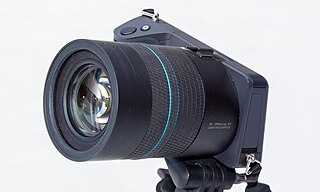
A light field camera, also known as a plenoptic camera, is a camera that captures information about the light field emanating from a scene; that is, the intensity of light in a scene, and also the precise direction that the light rays are traveling in space. This contrasts with conventional cameras, which record only light intensity at various wavelengths.
The following are common definitions related to the machine vision field.
Camera resectioning is the process of estimating the parameters of a pinhole camera model approximating the camera that produced a given photograph or video; it determines which incoming light ray is associated with each pixel on the resulting image. Basically, the process determines the pose of the pinhole camera.

Miniature faking, also known as diorama effect or diorama illusion, is a process in which a photograph of a life-size location or object is made to look like a photograph of a miniature scale model. Blurring parts of the photo simulates the shallow depth of field normally encountered in close-up photography, making the scene seem much smaller than it actually is; the blurring can be done either optically when the photograph is taken, or by digital postprocessing. Many diorama effect photographs are taken from a high angle to simulate the effect of looking down on a miniature. Tilt–shift photography is also associated with miniature faking.
The stereo cameras approach is a method of distilling a noisy video signal into a coherent data set that a computer can begin to process into actionable symbolic objects, or abstractions. Stereo cameras is one of many approaches used in the broader fields of computer vision and machine vision.
Range imaging is the name for a collection of techniques that are used to produce a 2D image showing the distance to points in a scene from a specific point, normally associated with some type of sensor device.
In computer vision and computer graphics, 3D reconstruction is the process of capturing the shape and appearance of real objects. This process can be accomplished either by active or passive methods. If the model is allowed to change its shape in time, this is referred to as non-rigid or spatio-temporal reconstruction.
A structured-light 3D scanner is a 3D scanning device for measuring the three-dimensional shape of an object using projected light patterns and a camera system.

A time-of-flight camera, also known as time-of-flight sensor, is a range imaging camera system for measuring distances between the camera and the subject for each point of the image based on time-of-flight, the round trip time of an artificial light signal, as provided by a laser or an LED. Laser-based time-of-flight cameras are part of a broader class of scannerless LIDAR, in which the entire scene is captured with each laser pulse, as opposed to point-by-point with a laser beam such as in scanning LIDAR systems. Time-of-flight camera products for civil applications began to emerge around 2000, as the semiconductor processes allowed the production of components fast enough for such devices. The systems cover ranges of a few centimeters up to several kilometers.
Computer stereo vision is the extraction of 3D information from digital images, such as those obtained by a CCD camera. By comparing information about a scene from two vantage points, 3D information can be extracted by examining the relative positions of objects in the two panels. This is similar to the biological process of stereopsis.
2D to 3D video conversion is the process of transforming 2D ("flat") film to 3D form, which in almost all cases is stereo, so it is the process of creating imagery for each eye from one 2D image.
This is a glossary of terms relating to computer graphics.