Differential interference contrast microscopy

Last updated
Micrasterias furcata imaged in transmitted DIC microscopy Micrasterias radiata.jpg
Micrasterias furcata imaged in transmitted DIC microscopy
Laser-induced optical damage in LiNbO3 under 150x Nomarski microscopy Laser-Induced Optical Damage in LiNbO3.jpg
Laser-induced optical damage in LiNbO3 under 150× Nomarski microscopy

Differential interference contrast (DIC) microscopy, also known as Nomarski interference contrast (NIC) or Nomarski microscopy, is an optical microscopy technique used to enhance the contrast in unstained, transparent samples. DIC works on the principle of interferometry to gain information about the optical path length of the sample, to see otherwise invisible features. A relatively complex optical system produces an image with the object appearing black to white on a grey background. This image is similar to that obtained by phase contrast microscopy but without the bright diffraction halo. The technique was invented by Francis Hughes Smith. [1] [ citation needed ] The "Smith DIK" was produced by Ernst Leitz Wetzlar in Germany and was difficult to manufacture. DIC was then developed further by Polish physicist Georges Nomarski in 1952. [2]

Contents

DIC works by separating a polarized light source into two orthogonally polarized mutually coherent parts which are spatially displaced (sheared) at the sample plane, and recombined before observation. The interference of the two parts at recombination is sensitive to their optical path difference (i.e. the product of refractive index and geometric path length). Adding an adjustable offset phase determining the interference at zero optical path difference in the sample, the contrast is proportional to the path length gradient along the shear direction, giving the appearance of a three-dimensional physical relief corresponding to the variation of optical density of the sample, emphasising lines and edges though not providing a topographically accurate image.
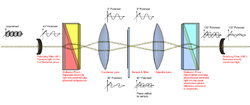
The light path

1. Unpolarised light enters the microscope and is polarised at 45°.

Polarised light is required for the technique to work.

2. The polarised light enters the first Nomarski-modified Wollaston prism and is separated into two rays polarised at 90° to each other, the sampling and reference rays.

Wollaston prisms are a type of prism made of two layers of a crystalline substance, such as quartz, which, due to the variation of refractive index depending on the polarisation of the light, splits the light according to its polarisation. The Nomarski prism causes the two rays to come to a focal point outside the body of the prism, and so allows greater flexibility when setting up the microscope, as the prism can be actively focused.

3. The two rays are focused by the condenser for passage through the sample. These two rays are focused so they will pass through two adjacent points in the sample, around 0.2 μm apart.

The sample is effectively illuminated by two coherent light sources, one with 0° polarisation and the other with 90° polarisation. These two illuminations are, however, not quite aligned, with one lying slightly offset with respect to the other.
The route of light through a DIC microscope. The two light beams should be parallel between condenser and objective DIC Light Path.png
The route of light through a DIC microscope. The two light beams should be parallel between condenser and objective

4. The rays travel through adjacent areas of the sample, separated by the shear. The separation is normally similar to the resolution of the microscope. They will experience different optical path lengths where the areas differ in refractive index or thickness. This causes a change in phase of one ray relative to the other due to the delay experienced by the wave in the more optically dense material.

The passage of many pairs of rays through pairs of adjacent points in the sample (and their absorbance, refraction and scattering by the sample) means an image of the sample will now be carried by both the 0° and 90° polarised light. These, if looked at individually, would be bright field images of the sample, slightly offset from each other. The light also carries information about the image invisible to the human eye, the phase of the light. This is vital later. The different polarisations prevent interference between these two images at this point.

5. The rays travel through the objective lens and are focused for the second Nomarski-modified Wollaston prism.

6. The second prism recombines the two rays into one polarised at 135°. The combination of the rays leads to interference, brightening or darkening the image at that point according to the optical path difference.

This prism overlays the two bright field images and aligns their polarisations so they can interfere. However, the images do not quite line up because of the offset in illumination – this means that instead of interference occurring between 2 rays of light that passed through the same point in the specimen, interference occurs between rays of light that went through adjacent points which therefore have a slightly different phase. Because the difference in phase is due to the difference in optical path length, this recombination of light causes "optical differentiation" of the optical path length, generating the image seen.

Image

The process of image production in a DIC microscope DIC Example.png
The process of image production in a DIC microscope

The image has the appearance of a three-dimensional object under very oblique illumination, causing strong light and dark shadows on the corresponding faces. The direction of apparent illumination is defined by the orientation of the Wollaston prisms.

As explained above, the image is generated from two identical bright field images being overlaid slightly offset from each other (typically around 0.2 μm), and the subsequent interference due to phase difference converting changes in phase (and so optical path length) to a visible change in darkness. This interference may be either constructive or destructive, giving rise to the characteristic appearance of three dimensions.

The typical phase difference giving rise to the interference is very small, very rarely being larger than 90° (a quarter of the wavelength). This is due to the similarity of refractive index of most samples and the media they are in: for example, a cell in water only has a refractive index difference of around 0.05. This small phase difference is important for the correct function of DIC, since if the phase difference at the joint between two substances is too large then the phase difference could reach 180° (half a wavelength), resulting in complete destructive interference and an anomalous dark region; if the phase difference reached 360° (a full wavelength), it would produce complete constructive interference, creating an anomalous bright region.

The image can be approximated (neglecting refraction and absorption due to the sample and the resolution limit of beam separation) as the differential of optical path length with respect to position across the sample along the shear, and so the differential of the refractive index (optical density) of the sample.

DIC images with different offset phases ph0 DIC Phase.jpg
DIC images with different offset phases φ0

The contrast can be adjusted using the offset phase, either by translating the objective Nomarski prism, or by a lambda/4 waveplate between polarizer and the condenser Normarski prism (De-Senarmont Compensation). The resulting contrast is going from dark-field for zero phase offset (intensity proportional to the square of the shear differential), to the typical relief seen for phase of ~5–90 degrees, to optical staining at 360 degrees, where the extinguished wavelength shifts with the phase differential.

When sequentially shifted images are collated, the phase-shift introduced by the object can be decoupled from unwanted non-interferometric artifacts, which typically results in an improvement in contrast, especially in turbid samples. [3]

Applications

Orientation-specific imaging of a transparent cuboid in DIC DIC Limitation Example.png
Orientation-specific imaging of a transparent cuboid in DIC
Partially developed photoresist in Nomarski DIC Al photoresist pattern developed via Nomarski DIC.jpg
Partially developed photoresist in Nomarski DIC

DIC is used for imaging live and unstained biological samples, such as a smear from a tissue culture or individual water borne single-celled organisms. Its resolution[ specify ] and clarity in conditions such as this are unrivaled among standard optical microscopy techniques.

Aluminum-silicon alloying pit made visible by Nomarski DIC 1-1-1 Pits from Aluminum Alloying.jpg
Aluminum–silicon alloying pit made visible by Nomarski DIC
Partially etched silicon dioxide in Nomarski DIC Partially etched silicon dioxide via Nomarski DIC.jpg
Partially etched silicon dioxide in Nomarski DIC

One non-biological area where DIC is used is in the analysis of planar silicon semiconductor processing. The thin (typically 100–1000 nm) films in silicon processing are often mostly transparent to visible light (e.g., silicon dioxide, silicon nitride and polycrystalline silicon), and defects in them or contamination lying on top of them become more visible. This also enables the determination of whether a feature is a pit in the substrate material or a blob of foreign material on top. Etched crystalline features gain a particularly striking appearance under DIC.

Image quality, when used under suitable conditions, is outstanding in resolution and almost entirely free of artifacts unlike phase contrast. However analysis of DIC images must always take into account the orientation of the Wollaston prisms and the apparent lighting direction, as features parallel to this will not be visible. This is, however, easily overcome by simply rotating the sample and observing changes in the image.

See also

Related Research Articles

<span class="mw-page-title-main">Microscopy</span> Viewing of objects which are too small to be seen with the naked eye

Microscopy is the technical field of using microscopes to view objects and areas of objects that cannot be seen with the naked eye. There are three well-known branches of microscopy: optical, electron, and scanning probe microscopy, along with the emerging field of X-ray microscopy.

<span class="mw-page-title-main">Microscope</span> Scientific instrument

A microscope is a laboratory instrument used to examine objects that are too small to be seen by the naked eye. Microscopy is the science of investigating small objects and structures using a microscope. Microscopic means being invisible to the eye unless aided by a microscope.

<span class="mw-page-title-main">Optics</span> Branch of physics that studies light

Optics is the branch of physics that studies the behaviour and properties of light, including its interactions with matter and the construction of instruments that use or detect it. Optics usually describes the behaviour of visible, ultraviolet, and infrared light. Because light is an electromagnetic wave, other forms of electromagnetic radiation such as X-rays, microwaves, and radio waves exhibit similar properties.

<span class="mw-page-title-main">Refractive index</span> Ratio of the speed of light in vacuum to that in the medium

In optics, the refractive index of an optical medium is a dimensionless number that gives the indication of the light bending ability of that medium.

<span class="mw-page-title-main">Optical microscope</span> Microscope that uses visible light

The optical microscope, also referred to as a light microscope, is a type of microscope that commonly uses visible light and a system of lenses to generate magnified images of small objects. Optical microscopes are the oldest design of microscope and were possibly invented in their present compound form in the 17th century. Basic optical microscopes can be very simple, although many complex designs aim to improve resolution and sample contrast.

<span class="mw-page-title-main">Interferometry</span> Measurement method using interference of waves

Interferometry is a technique which uses the interference of superimposed waves to extract information. Interferometry typically uses electromagnetic waves and is an important investigative technique in the fields of astronomy, fiber optics, engineering metrology, optical metrology, oceanography, seismology, spectroscopy, quantum mechanics, nuclear and particle physics, plasma physics, remote sensing, biomolecular interactions, surface profiling, microfluidics, mechanical stress/strain measurement, velocimetry, optometry, and making holograms.

<span class="mw-page-title-main">Prism (optics)</span> Transparent optical element with flat, polished surfaces that refract light

An optical prism is a transparent optical element with flat, polished surfaces that are designed to refract light. At least one surface must be angled — elements with two parallel surfaces are not prisms. The most familiar type of optical prism is the triangular prism, which has a triangular base and rectangular sides. Not all optical prisms are geometric prisms, and not all geometric prisms would count as an optical prism. Prisms can be made from any material that is transparent to the wavelengths for which they are designed. Typical materials include glass, acrylic and fluorite.

Optics is the branch of physics which involves the behavior and properties of light, including its interactions with matter and the construction of instruments that use or detect it. Optics usually describes the behavior of visible, ultraviolet, and infrared light. Because light is an electromagnetic wave, other forms of electromagnetic radiation such as X-rays, microwaves, and radio waves exhibit similar properties.

<span class="mw-page-title-main">X-ray microscope</span> Type of microscope that uses X-rays

An X-ray microscope uses electromagnetic radiation in the X-ray band to produce magnified images of objects. Since X-rays penetrate most objects, there is no need to specially prepare them for X-ray microscopy observations.

<span class="mw-page-title-main">Metallography</span>

Metallography is the study of the physical structure and components of metals, by using microscopy.

Phase-contrast imaging is a method of imaging that has a range of different applications. It measures differences in the refractive index of different materials to differentiate between structures under analysis. In conventional light microscopy, phase contrast can be employed to distinguish between structures of similar transparency, and to examine crystals on the basis of their double refraction. This has uses in biological, medical and geological science. In X-ray tomography, the same physical principles can be used to increase image contrast by highlighting small details of differing refractive index within structures that are otherwise uniform. In transmission electron microscopy (TEM), phase contrast enables very high resolution (HR) imaging, making it possible to distinguish features a few Angstrom apart.

X-ray optics is the branch of optics that manipulates X-rays instead of visible light. It deals with focusing and other ways of manipulating the X-ray beams for research techniques such as X-ray crystallography, X-ray fluorescence, small-angle X-ray scattering, X-ray microscopy, X-ray phase-contrast imaging, and X-ray astronomy.

<span class="mw-page-title-main">Nomarski prism</span> Type of polarizer

A Nomarski prism is a modification of the Wollaston prism that is used in differential interference contrast microscopy. It is named after its inventor, Polish and naturalized-French physicist Georges Nomarski. Like the Wollaston prism, the Nomarski prism consists of two birefringent crystal wedges cemented together at the hypotenuse. One of the wedges is identical to a conventional Wollaston wedge and has the optical axis oriented parallel to the surface of the prism. The second wedge of the prism is modified by cutting the crystal so that the optical axis is oriented obliquely with respect to the flat surface of the prism. The Nomarski modification causes the light rays to come to a focal point outside the body of the prism, and allows greater flexibility so that when setting up the microscope the prism can be actively focused.

<span class="mw-page-title-main">Bright-field microscopy</span> Optical microscopy illumination technique

Bright-field microscopy (BF) is the simplest of all the optical microscopy illumination techniques. Sample illumination is transmitted white light, and contrast in the sample is caused by attenuation of the transmitted light in dense areas of the sample. Bright-field microscopy is the simplest of a range of techniques used for illumination of samples in light microscopes, and its simplicity makes it a popular technique. The typical appearance of a bright-field microscopy image is a dark sample on a bright background, hence the name.

<span class="mw-page-title-main">Phase-contrast microscopy</span> Optical microscopy technique

Phase-contrast microscopy (PCM) is an optical microscopy technique that converts phase shifts in light passing through a transparent specimen to brightness changes in the image. Phase shifts themselves are invisible, but become visible when shown as brightness variations.

Classical interference microscopy, also called quantitative interference microscopy, uses two separate light beams with much greater lateral separation than that used in phase contrast microscopy or in differential interference microscopy (DIC).

<span class="mw-page-title-main">Optical sectioning</span> Imaging of focal planes within a thick sample

Optical sectioning is the process by which a suitably designed microscope can produce clear images of focal planes deep within a thick sample. This is used to reduce the need for thin sectioning using instruments such as the microtome. Many different techniques for optical sectioning are used and several microscopy techniques are specifically designed to improve the quality of optical sectioning.

<span class="mw-page-title-main">Interference colour chart</span>

In optical mineralogy, an interference colour chart, also known as the Michel-Levy chart, is a tool first developed by Auguste Michel-Lévy to identify minerals in thin section using a petrographic microscope. With a known thickness of the thin section, minerals have specific and predictable colours in cross-polarized light, and this chart can help identify minerals. The colours are produced by the difference in speed in the fast and slow rays, also known as birefringence.

<span class="mw-page-title-main">Interference reflection microscopy</span>

Interference reflection microscopy (IRM), also called Reflection Interference Contrast Microscopy (RICM) or Reflection Contrast Microscopy (RCM) depending on the context, is an optical microscopy technique that leverages interference effects to form an image of an object on a glass surface. The intensity of the signal is a measure of proximity of the object to the glass surface. This technique can be used to study events at the cell membrane without the use of a (fluorescent) label as is the case for TIRF microscopy.

<span class="mw-page-title-main">Hoffman modulation contrast microscopy</span> Optical microscopy technique

Hoffman modulation contrast microscopy is an optical microscopy technique for enhancing the contrast in unstained biological specimens. The technique was invented by Robert Hoffman in 1975. Like differential interference contrast microscopy, contrast is increased by using components in the light path which convert phase gradients in the specimen into differences in light intensity that are rendered in an image that appears three-dimensional. The 3D appearance may be misleading, as a feature which appears to cast a shadow may not necessarily have a distinct physical geometry corresponding to the shadow. The technique is particularly suitable for optical sectioning at lower magnifications.

References

  1. US2601175A,Hughes, Smith Francis,"Interference microscope",issued 1952-06-17
  2. Lang, Walter (1968). "Nomarski differential interference-contrast microscopy" (PDF). ZEISS Information. 70: 114–120. Retrieved 31 August 2016.
  3. Nguyen, T.H.; Kandel, M.E.; Rubessa, M.; et al. (2017). "Gradient light interference microscopy for 3D imaging of unlabeled specimens". Nat Commun. 8 (210): 210. Bibcode:2017NatCo...8..210N. doi:10.1038/s41467-017-00190-7. PMC   5547102 . PMID   28785013.