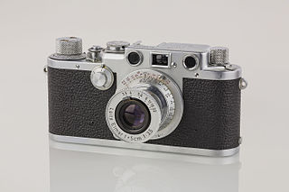
A camera is an optical instrument that captures images. Most cameras can capture 2D images, while some more advanced models can capture 3D images. At a basic level, most cameras consist of a sealed box, with a small hole that allows light to pass through and capture an image on a light-sensitive surface. Cameras have various mechanisms to control how light falls onto the light-sensitive surface, including lenses that focus the light and a shutter that determines the amount of time the photosensitive surface is exposed to the light.
The focal length of an optical system is a measure of how strongly the system converges or diverges light; it is the inverse of the system's optical power. A positive focal length indicates that a system converges light, while a negative focal length indicates that the system diverges light. A system with a shorter focal length bends the rays more sharply, bringing them to a focus in a shorter distance or diverging them more quickly. For the special case of a thin lens in air, a positive focal length is the distance over which initially collimated (parallel) rays are brought to a focus, or alternatively a negative focal length indicates how far in front of the lens a point source must be located to form a collimated beam. For more general optical systems, the focal length has no intuitive meaning; it is simply the inverse of the system's optical power.

Astrophotography, also known as astronomical imaging, is the photography or imaging of astronomical objects, celestial events, or areas of the night sky. The first photograph of an astronomical object was taken in 1840, but it was not until the late 19th century that advances in technology allowed for detailed stellar photography. Besides being able to record the details of extended objects such as the Moon, Sun, and planets, modern astrophotography has the ability to image objects invisible to the human eye such as dim stars, nebulae, and galaxies. This is accomplished through long time exposure as both film and digital cameras can accumulate and sum photons over long periods of time.

In optics, a circle of confusion (CoC) is an optical spot caused by a cone of light rays from a lens not coming to a perfect focus when imaging a point source. It is also known as disk of confusion, circle of indistinctness, blur circle, or blur spot.
The angle of view is the decisive variable for the visual perception of the size or projection of the size of an object.

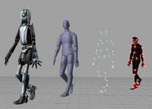
Stereoscopy is a technique for creating or enhancing the illusion of depth in an image by means of stereopsis for binocular vision. The word stereoscopy derives from Greek στερεός (stereos) 'firm, solid', and σκοπέω (skopeō) 'to look, to see'. Any stereoscopic image is called a stereogram. Originally, stereogram referred to a pair of stereo images which could be viewed using a stereoscope.

A 3D projection is a design technique used to display a three-dimensional (3D) object on a two-dimensional (2D) surface. These projections rely on visual perspective and aspect analysis to project a complex object for viewing capability on a simpler plane.

Ray casting is the methodological basis for 3D CAD/CAM solid modeling and image rendering. It is essentially the same as ray tracing for computer graphics where virtual light rays are "cast" or "traced" on their path from the focal point of a camera through each pixel in the camera sensor to determine what is visible along the ray in the 3D scene. The term "Ray Casting" was introduced by Scott Roth while at the General Motors Research Labs from 1978–1980. His paper, "Ray Casting for Modeling Solids", describes modeled solid objects by combining primitive solids, such as blocks and cylinders, using the set operators union (+), intersection (&), and difference (-). The general idea of using these binary operators for solid modeling is largely due to Voelcker and Requicha's geometric modelling group at the University of Rochester. See Solid modeling for a broad overview of solid modeling methods. This figure on the right shows a U-Joint modeled from cylinders and blocks in a binary tree using Roth's ray casting system, circa 1979.

In 3D computer graphics, hidden-surface determination is the process of identifying what surfaces and parts of surfaces can be seen from a particular viewing angle. A hidden-surface determination algorithm is a solution to the visibility problem, which was one of the first major problems in the field of 3D computer graphics. The process of hidden-surface determination is sometimes called hiding, and such an algorithm is sometimes called a hider. When referring to line rendering it is known as hidden-line removal. Hidden-surface determination is necessary to render a scene correctly, so that one may not view features hidden behind the model itself, allowing only the naturally viewable portion of the graphic to be visible.
2.5D perspective refers to gameplay or movement in a video game or virtual reality environment that is restricted to a two-dimensional (2D) plane with little to no access to a third dimension in a space that otherwise appears to be three-dimensional and is often simulated and rendered in a 3D digital environment.

In architecture and building engineering, a floor plan is a technical drawing to scale, showing a view from above, of the relationships between rooms, spaces, traffic patterns, and other physical features at one level of a structure.

Magnification is the process of enlarging the apparent size, not physical size, of something. This enlargement is quantified by a calculated number also called "magnification". When this number is less than one, it refers to a reduction in size, sometimes called magnification or de-magnification.

A 3D display is a display device capable of conveying depth to the viewer. Many 3D displays are stereoscopic displays, which produce a basic 3D effect by means of stereopsis, but can cause eye strain and visual fatigue. Newer 3D displays such as holographic and light field displays produce a more realistic 3D effect by combining stereopsis and accurate focal length for the displayed content. Newer 3D displays in this manner cause less visual fatigue than classical stereoscopic displays.
In photography, a shutter is a device that allows light to pass for a determined period, exposing photographic film or a photosensitive digital sensor to light in order to capture a permanent image of a scene. A shutter can also be used to allow pulses of light to pass outwards, as seen in a movie projector or a signal lamp. A shutter of variable speed is used to control exposure time of the film. The shutter is constructed so that it automatically closes after a certain required time interval. The speed of the shutter is controlled by a ring outside the camera, on which various timings are marked.

In three-dimensional geometry, a parallel projection is a projection of an object in three-dimensional space onto a fixed plane, known as the projection plane or image plane, where the rays, known as lines of sight or projection lines, are parallel to each other. It is a basic tool in descriptive geometry. The projection is called orthographic if the rays are perpendicular (orthogonal) to the image plane, and oblique or skew if they are not.

A lenticular lens is an array of lenses, designed so that when viewed from slightly different angles, different parts of the image underneath are shown. The most common example is the lenses used in lenticular printing, where the technology is used to give an illusion of depth, or to make images that appear to change or move as the image is viewed from different angles.
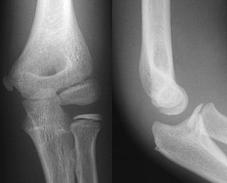
Projectional radiography, also known as conventional radiography, is a form of radiography and medical imaging that produces two-dimensional images by x-ray radiation. The image acquisition is generally performed by radiographers, and the images are often examined by radiologists. Both the procedure and any resultant images are often simply called "X-ray". Plain radiography or roentgenography generally refers to projectional radiography. Plain radiography can also refer to radiography without a radiocontrast agent or radiography that generates single static images, as contrasted to fluoroscopy, which are technically also projectional.
In technical drawing and computer graphics, a multiview projection is a technique of illustration by which a standardized series of orthographic two-dimensional pictures are constructed to represent the form of a three-dimensional object. Up to six pictures of an object are produced, with each projection plane parallel to one of the coordinate axes of the object. The views are positioned relative to each other according to either of two schemes: first-angle or third-angle projection. In each, the appearances of views may be thought of as being projected onto planes that form a six-sided box around the object. Although six different sides can be drawn, usually three views of a drawing give enough information to make a three-dimensional object. These views are known as front view, top view and end view. Other names for these views include plan, elevation and section. When the plane or axis of the object depicted is not parallel to the projection plane, and where multiple sides of an object are visible in the same image, it is called an auxiliary view.
A variety of computer graphic techniques have been used to display video game content throughout the history of video games. The predominance of individual techniques have evolved over time, primarily due to hardware advances and restrictions such as the processing power of central or graphics processing units.
In 3D computer graphics and computer vision, a depth map is an image or image channel that contains information relating to the distance of the surfaces of scene objects from a viewpoint. The term is related to depth buffer, Z-buffer, Z-buffering, and Z-depth. The "Z" in these latter terms relates to a convention that the central axis of view of a camera is in the direction of the camera's Z axis, and not to the absolute Z axis of a scene.