
Technical drawing, drafting or drawing, is the act and discipline of composing drawings that visually communicate how something functions or is constructed.

Isometric projection is a method for visually representing three-dimensional objects in two dimensions in technical and engineering drawings. It is an axonometric projection in which the three coordinate axes appear equally foreshortened and the angle between any two of them is 120 degrees.

An engineering drawing is a type of technical drawing that is used to convey information about an object. A common use is to specify the geometry necessary for the construction of a component and is called a detail drawing. Usually, a number of drawings are necessary to completely specify even a simple component. The drawings are linked together by a master drawing or assembly drawing which gives the drawing numbers of the subsequent detailed components, quantities required, construction materials and possibly 3D images that can be used to locate individual items. Although mostly consisting of pictographic representations, abbreviations and symbols are used for brevity and additional textual explanations may also be provided to convey the necessary information.

Orthographic projection is a means of representing three-dimensional objects in two dimensions. Orthographic projection is a form of parallel projection in which all the projection lines are orthogonal to the projection plane, resulting in every plane of the scene appearing in affine transformation on the viewing surface. The obverse of an orthographic projection is an oblique projection, which is a parallel projection in which the projection lines are not orthogonal to the projection plane.

A 3D projection is a design technique used to display a three-dimensional (3D) object on a two-dimensional (2D) surface. These projections rely on visual perspective and aspect analysis to project a complex object for viewing capability on a simpler plane.
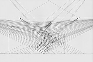
Linear or point-projection perspective is one of two types of graphical projection perspective in the graphic arts; the other is parallel projection. Linear perspective is an approximate representation, generally on a flat surface, of an image as it is seen by the eye. Perspective drawing is useful for representing a three-dimensional scene in a two-dimensional medium, like paper.

In geometry, a point at infinity or ideal point is an idealized limiting point at the "end" of each line.
Axonometric projection is a type of orthographic projection used for creating a pictorial drawing of an object, where the object is rotated around one or more of its axes to reveal multiple sides.

Descriptive geometry is the branch of geometry which allows the representation of three-dimensional objects in two dimensions by using a specific set of procedures. The resulting techniques are important for engineering, architecture, design and in art. The theoretical basis for descriptive geometry is provided by planar geometric projections. The earliest known publication on the technique was "Underweysung der Messung mit dem Zirckel und Richtscheyt", published in Linien, Nuremberg: 1525, by Albrecht Dürer. Italian architect Guarino Guarini was also a pioneer of projective and descriptive geometry, as is clear from his Placita Philosophica (1665), Euclides Adauctus (1671) and Architettura Civile, anticipating the work of Gaspard Monge (1746–1818), who is usually credited with the invention of descriptive geometry. Gaspard Monge is usually considered the "father of descriptive geometry" due to his developments in geometric problem solving. His first discoveries were in 1765 while he was working as a draftsman for military fortifications, although his findings were published later on.
Oblique projection is a simple type of technical drawing of graphical projection used for producing two-dimensional (2D) images of three-dimensional (3D) objects.

Curvilinear perspective, also five-point perspective, is a graphical projection used to draw 3D objects on 2D surfaces. It was formally codified in 1968 by the artists and art historians André Barre and Albert Flocon in the book La Perspective curviligne, which was translated into English in 1987 as Curvilinear Perspective: From Visual Space to the Constructed Image and published by the University of California Press. Curvilinear perspective is sometimes colloquially called fisheye perspective, by analogy to a fisheye lens. In computer animation and motion graphics, a five-point perspective is sometimes referenced as tiny planet.

A vanishing point is a point on the image plane of a perspective rendering where the two-dimensional perspective projections of mutually parallel lines in three-dimensional space appear to converge. When the set of parallel lines is perpendicular to a picture plane, the construction is known as one-point perspective, and their vanishing point corresponds to the oculus, or "eye point", from which the image should be viewed for correct perspective geometry. Traditional linear drawings use objects with one to three sets of parallels, defining one to three vanishing points.
2.5D perspective refers to gameplay or movement in a video game or virtual reality environment that is restricted to a two-dimensional (2D) plane with little to no access to a third dimension in a space that otherwise appears to be three-dimensional and is often simulated and rendered in a 3D digital environment.
In painting, photography, graphical perspective and descriptive geometry, a picture plane is an image plane located between the "eye point" and the object being viewed and is usually coextensive to the material surface of the work. It is ordinarily a vertical plane perpendicular to the sightline to the object of interest.
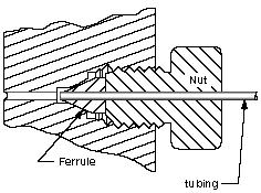
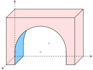
In geometry and science, a cross section is the non-empty intersection of a solid body in three-dimensional space with a plane, or the analog in higher-dimensional spaces. Cutting an object into slices creates many parallel cross-sections. The boundary of a cross-section in three-dimensional space that is parallel to two of the axes, that is, parallel to the plane determined by these axes, is sometimes referred to as a contour line; for example, if a plane cuts through mountains of a raised-relief map parallel to the ground, the result is a contour line in two-dimensional space showing points on the surface of the mountains of equal elevation.

Real-time computer graphics or real-time rendering is the sub-field of computer graphics focused on producing and analyzing images in real time. The term can refer to anything from rendering an application's graphical user interface (GUI) to real-time image analysis, but is most often used in reference to interactive 3D computer graphics, typically using a graphics processing unit (GPU). One example of this concept is a video game that rapidly renders changing 3D environments to produce an illusion of motion.
In three-dimensional geometry, a parallel projection is a projection of an object in three-dimensional space onto a fixed plane, known as the projection plane or image plane, where the rays, known as lines of sight or projection lines, are parallel to each other. It is a basic tool in descriptive geometry. The projection is called orthographic if the rays are perpendicular (orthogonal) to the image plane, and oblique or skew if they are not.
Planar projections are the subset of 3D graphical projections constructed by linearly mapping points in three-dimensional space to points on a two-dimensional projection plane. The projected point on the plane is chosen such that it is collinear with the corresponding three-dimensional point and the centre of projection. The lines connecting these points are commonly referred to as projectors.
In technical drawing and computer graphics, a multiview projection is a technique of illustration by which a standardized series of orthographic two-dimensional pictures are constructed to represent the form of a three-dimensional object. Up to six pictures of an object are produced, with each projection plane parallel to one of the coordinate axes of the object. The views are positioned relative to each other according to either of two schemes: first-angle or third-angle projection. In each, the appearances of views may be thought of as being projected onto planes that form a six-sided box around the object. Although six different sides can be drawn, usually three views of a drawing give enough information to make a three-dimensional object. These views are known as front view, top view and end view. Other names for these views include plan, elevation and section. When the plane or axis of the object depicted is not parallel to the projection plane, and where multiple sides of an object are visible in the same image, it is called an auxiliary view.
Axonometry is a graphical procedure belonging to descriptive geometry that generates a planar image of a three-dimensional object. The term "axonometry" means "to measure along axes", and indicates that the dimensions and scaling of the coordinate axes play a crucial role. The result of an axonometric procedure is a uniformly-scaled parallel projection of the object. In general, the resulting parallel projection is oblique ; but in special cases the result is orthographic, which in this context is called an orthogonal axonometry.

 Perspective projection of triangle ABC on plane Π from point S.
 Axonometric projection on projection plane Π
 A cube in two-point perspective
 Simulated rays of light travel from the object, through the projection plane, and to the viewer's eye or camera. This is the basis for graphical perspective.
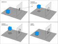 Various graphical projections and how they are produced


