Example of four different 2D representations of the same 3D object
Example object and its six principal views
Different orthographic projections of a house. The file below shows three principal views and one that shows the true lengths in the plane of the roof. (The conicdormer shows parts of an ellipse and a hyperbola.)
Descriptive geometry is the branch of geometry which allows the representation of three-dimensional objects in two dimensions by using a specific set of procedures. The resulting techniques are important for engineering, architecture, design and in art.[1] The theoretical basis for descriptive geometry is provided by planar geometric projections.
The earliest known publication on the technique was "Underweysung der Messung mit dem Zirckel und Richtscheyt" (Observation of the measurement with the compass and spirit level), published in Linien, Nuremberg: 1525, by Albrecht Dürer. Italian architect Guarino Guarini was also a pioneer of projective and descriptive geometry, as is clear from his Placita Philosophica (1665), Euclides Adauctus (1671) and Architettura Civile (1686—not published until 1737). Gaspard Monge (1746–1818) is usually credited with the invention of descriptive geometry,[2][3] called the "father of descriptive geometry" due to his developments in geometric problem solving. His first discoveries were in 1765 while he was working as a draftsman for military fortifications, although his findings were published later on.[4]
Monge's protocols allow an imaginary object to be drawn in such a way that it may be modeled in three dimensions. All geometric aspects of the imaginary object are accounted for in true size/to-scale and shape, and can be imaged as seen from any position in space. All images are represented on a two-dimensional surface.
Descriptive geometry uses the image-creating technique of imaginary, parallel projectors emanating from an imaginary object and intersecting an imaginary plane of projection at right angles. The cumulative points of intersections create the desired image.
Protocols
Project two images of an object into mutually perpendicular, arbitrary directions. Each image view accommodates three dimensions of space, two dimensions displayed as full-scale, mutually-perpendicular axes and one as an invisible (point view) axis receding into the image space (depth). Each of the two adjacent image views shares a full-scale view of one of the three dimensions of space.
Either of these images may serve as the beginning point for a third projected view. The third view may begin a fourth projection, and on ad infinitum. These sequential projections each represent a circuitous, 90° turn in space in order to view the object from a different direction.
Each new projection utilizes a dimension in full scale that appears as point-view dimension in the previous view. To achieve the full-scale view of this dimension and accommodate it within the new view requires one to ignore the previous view and proceed to the second previous view where this dimension appears in full-scale.
Each new view may be created by projecting into any of an infinite number of directions, perpendicular to the previous direction of projection. (Envision the many directions of the spokes of a wagon wheel each perpendicular to the direction of the axle.) The result is one of stepping circuitously about an object in 90° turns and viewing the object from each step. Each new view is added as an additional view to an orthographic projection layout display and appears in an "unfolding of the glass box model".
Aside from the orthographic, six standard principal views (front; right side; left side; top; bottom; rear), descriptive geometry strives to yield four basic solution views: the true length of a line (i.e., full size, not foreshortened), the point view (end view) of a line, the true shape of a plane (i.e., full size to scale, or not foreshortened), and the edge view of a plane (i.e., view of a plane with the line of sight perpendicular to the line of sight associated with the line of sight for producing the true shape of a plane). These often serve to determine the direction of projection for the subsequent view. By the 90° circuitous stepping process, projecting in any direction from the point view of a line yields its true length view; projecting in a direction parallel to a true length line view yields its point view, projecting the point view of any line on a plane yields the plane's edge view; projecting in a direction perpendicular to the edge view of a plane will yield the true shape (to scale) view. These various views may be called upon to help solve engineering problems posed by solid-geometry principles.
Heuristics
There is heuristic value to studying descriptive geometry. It promotes visualization and spatial analytical abilities, as well as the intuitive ability to recognize the direction of viewing for best presenting a geometric problem for solution. Representative examples:
The best direction to view
Two skew lines (pipes, perhaps) in general positions in order to determine the location of their shortest connector (common perpendicular)
Two skew lines (pipes) in general positions such that their shortest connector is seen in full scale
Two skew lines in general positions such the shortest connector parallel to a given plane is seen in full scale (say, to determine the position and the dimension of the shortest connector at a constant distance from a radiating surface)
A plane surface such that a hole drilled perpendicular is seen in full scale, as if looking through the hole (say, to test for clearances with other drilled holes)
A plane equidistant from two skew lines in general positions (say, to confirm safe radiation distance?)
The shortest distance from a point to a plane (say, to locate the most economical position for bracing)
The line of intersection between two surfaces, including curved surfaces (say, for the most economical sizing of sections?)
The true size of the angle between two planes
A standard for presenting computer-modeling views analogous to orthographic, sequential projections has not yet been adopted. One candidate for such is presented in the illustrations below. The images in the illustrations were created using three-dimensional, engineering computer graphics.
Three-dimensional computer modeling produces virtual space behind the screen and may produce any view of a model from any direction within this virtual space. It does so without the need for adjacent orthographic views and therefore may seem to render the circuitous, stepping protocol of descriptive geometry obsolete. However, since descriptive geometry is the science of the legitimate or allowable imaging of three or more dimensional space, on a flat plane, it is an indispensable study, to enhance computer modeling possibilities.
Examples
Finding the shortest connector line QT between two given skew lines PR and SU
Example of the use of descriptive geometry to find the shortest connector between two skew lines, PR & SU. The red, yellow and green highlights show distances which are the same for projections of point P.
Given the X, Y and Z coordinates of P, R, S and U, projections 1 and 2 are drawn to scale on the X-Y and X-Z planes, respectively. Projections 1 and 2 are delineated by hinge line H1,2, and aligned such that each point projects perpendicularly across the hinge line (P1:P2, R1:R2, S1:S2, U1:U2).
To get a true view (length in the projection is equal to length in 3D space) of one of the lines: SU in this example, the projection 3 view is chosen perpendicular to S2U2 by drawing a hinge line H2,3 parallel to S2U2. To get an end view of SU, the projection 4 view is chosen is perpendicular to the true view of line S3U3 by drawing a hinge line H3,4 perpendicular to S3U3. The perpendicular QT is the true length of the connector and its distance d gives the shortest distance between PR and SU.
To locate points Q and T on these lines giving this shortest distance, projection 5 is drawn with hinge line H4,5 perpendicular to QT and parallel to P4R4, making both P5R5 and S5U5 true views (any projection of an end view is a true view). Projecting the intersection of these lines, Q5 and T5 back to projection 1 (magenta lines and labels) allows their coordinates to be read off the X, Y and Z axes.
General solutions
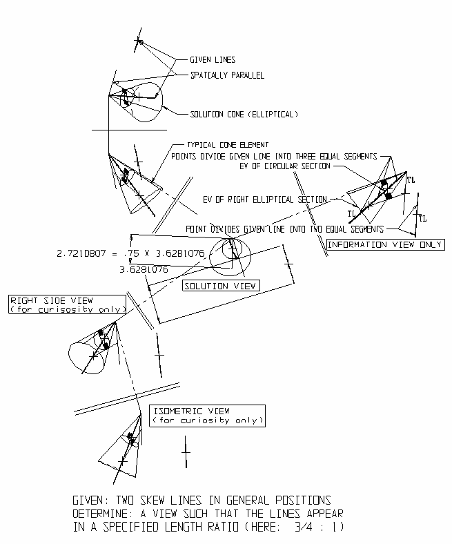
General solutions are a class of solutions within descriptive geometry that contain all possible solutions to a problem. The general solution is represented by a single, three-dimensional object, usually a cone, the directions of the elements of which are the desired direction of viewing (projection) for any of an infinite number of solution views.
For example: To find the general solution such that two, unequal length, skew lines in general positions (say, rockets in flight?) appear:
Equal length
Equal length and parallel
Equal length and perpendicular (say, for ideal targeting of at least one)
Equal to lengths of a specified ratio
others.
In the examples, the general solution for each desired characteristic solution is a cone, each element of which produces one of an infinite number of solution views. When two or more characteristics of, say those listed above, are desired (and for which a solution exists) projecting in the direction of either of the two elements of intersections (one element, if cones are tangent) between the two cones produces the desired solution view. If the cones do not intersect a solution does not exist. The examples below are annotated to show the descriptive geometric principles used in the solutions. TL = True-Length; EV = Edge View.
Figs. 1-3 below demonstrate (1) Descriptive geometry, general solutions and (2) simultaneously, a potential standard for presenting such solutions in orthographic, multiview, layout formats.
The potential standard employs two adjacent, standard, orthographic views (here, Front and Top) with a standard "folding line" between. As there is no subsequent need to 'circuitously step' 90° around the object, in standard, two-step sequences in order to arrive at a solution view (it is possible to go directly to the solution view), this shorter protocol is accounted for in the layout. Where the one step protocol replaces the two-step protocol, "double folding" lines are used. In other words, when one crosses the double lines he is not making a circuitous 90° turn but a non-orthodirectional turn directly to the solution view. As most engineering computer graphics packages automatically generates the six principal views of the glass box model, as well as an isometric view, these views are sometimes added out of heuristic curiosity.
↑ Bianchini, Carlo (2012). "Stereotomy Role in Guarino Guarini's Space Research". Nuts and Bolts of Construction History. 1: 257–263. ISBN978-2-7084-0929-3.
This page is based on this Wikipedia article Text is available under the CC BY-SA 4.0 license; additional terms may apply. Images, videos and audio are available under their respective licenses.