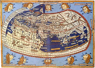
In cartography, a map projection is any of a broad set of transformations employed to represent the curved two-dimensional surface of a globe on a plane. In a map projection, coordinates, often expressed as latitude and longitude, of locations from the surface of the globe are transformed to coordinates on a plane. Projection is a necessary step in creating a two-dimensional map and is one of the essential elements of cartography.

Technical drawing, drafting or drawing, is the act and discipline of composing drawings that visually communicate how something functions or is constructed.

Isometric projection is a method for visually representing three-dimensional objects in two dimensions in technical and engineering drawings. It is an axonometric projection in which the three coordinate axes appear equally foreshortened and the angle between any two of them is 120 degrees.

An engineering drawing is a type of technical drawing that is used to convey information about an object. A common use is to specify the geometry necessary for the construction of a component and is called a detail drawing. Usually, a number of drawings are necessary to completely specify even a simple component. These drawings are linked together by a "master drawing." This "master drawing" is more commonly known as an assembly drawing. The assembly drawing gives the drawing numbers of the subsequent detailed components, quantities required, construction materials and possibly 3D images that can be used to locate individual items. Although mostly consisting of pictographic representations, abbreviations and symbols are used for brevity and additional textual explanations may also be provided to convey the necessary information.

Orthographic projection is a means of representing three-dimensional objects in two dimensions. Orthographic projection is a form of parallel projection in which all the projection lines are orthogonal to the projection plane, resulting in every plane of the scene appearing in affine transformation on the viewing surface. The obverse of an orthographic projection is an oblique projection, which is a parallel projection in which the projection lines are not orthogonal to the projection plane.

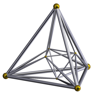
In four-dimensional geometry, the 24-cell is the convex regular 4-polytope (four-dimensional analogue of a Platonic solid) with Schläfli symbol {3,4,3}. It is also called C24, or the icositetrachoron, octaplex (short for "octahedral complex"), icosatetrahedroid, octacube, hyper-diamond or polyoctahedron, being constructed of octahedral cells.

A 3D projection is a design technique used to display a three-dimensional (3D) object on a two-dimensional (2D) surface. These projections rely on visual perspective and aspect analysis to project a complex object for viewing capability on a simpler plane.
Axonometric projection is a type of orthographic projection used for creating a pictorial drawing of an object, where the object is rotated around one or more of its axes to reveal multiple sides.

Descriptive geometry is the branch of geometry which allows the representation of three-dimensional objects in two dimensions by using a specific set of procedures. The resulting techniques are important for engineering, architecture, design and in art. The theoretical basis for descriptive geometry is provided by planar geometric projections. The earliest known publication on the technique was "Underweysung der Messung mit dem Zirckel und Richtscheyt", published in Linien, Nuremberg: 1525, by Albrecht Dürer. Italian architect Guarino Guarini was also a pioneer of projective and descriptive geometry, as is clear from his Placita Philosophica (1665), Euclides Adauctus (1671) and Architettura Civile, anticipating the work of Gaspard Monge (1746–1818), who is usually credited with the invention of descriptive geometry. Gaspard Monge is usually considered the "father of descriptive geometry" due to his developments in geometric problem solving. His first discoveries were in 1765 while he was working as a draftsman for military fortifications, although his findings were published later on.
Oblique projection is a simple type of technical drawing of graphical projection used for producing two-dimensional (2D) images of three-dimensional (3D) objects.

In architecture and building engineering, a floor plan is a technical drawing to scale, showing a view from above, of the relationships between rooms, spaces, traffic patterns, and other physical features at one level of a structure.

Orthographic projection in cartography has been used since antiquity. Like the stereographic projection and gnomonic projection, orthographic projection is a perspective projection in which the sphere is projected onto a tangent plane or secant plane. The point of perspective for the orthographic projection is at infinite distance. It depicts a hemisphere of the globe as it appears from outer space, where the horizon is a great circle. The shapes and areas are distorted, particularly near the edges.
In geometry, the 16-cell is the regular convex 4-polytope (four-dimensional analogue of a Platonic solid) with Schläfli symbol {3,3,4}. It is one of the six regular convex 4-polytopes first described by the Swiss mathematician Ludwig Schläfli in the mid-19th century. It is also called C16, hexadecachoron, or hexdecahedroid [sic?].
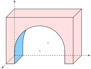
In geometry and science, a cross section is the non-empty intersection of a solid body in three-dimensional space with a plane, or the analog in higher-dimensional spaces. Cutting an object into slices creates many parallel cross-sections. The boundary of a cross-section in three-dimensional space that is parallel to two of the axes, that is, parallel to the plane determined by these axes, is sometimes referred to as a contour line; for example, if a plane cuts through mountains of a raised-relief map parallel to the ground, the result is a contour line in two-dimensional space showing points on the surface of the mountains of equal elevation.
In three-dimensional geometry, a parallel projection is a projection of an object in three-dimensional space onto a fixed plane, known as the projection plane or image plane, where the rays, known as lines of sight or projection lines, are parallel to each other. It is a basic tool in descriptive geometry. The projection is called orthographic if the rays are perpendicular (orthogonal) to the image plane, and oblique or skew if they are not.
A scale ruler is a tool for measuring lengths and transferring measurements at a fixed ratio of length; two common examples are an architect's scale and engineer's scale. In scientific and engineering terminology, a device to measure linear distance and create proportional linear measurements is called a scale. A device for drawing straight lines is a straight edge or ruler. In common usage, both are referred to as a ruler.

Plans are a set of drawings or two-dimensional diagrams used to describe a place or object, or to communicate building or fabrication instructions. Usually plans are drawn or printed on paper, but they can take the form of a digital file.
In technical drawing and computer graphics, a multiview projection is a technique of illustration by which a standardized series of orthographic two-dimensional pictures are constructed to represent the form of a three-dimensional object. Up to six pictures of an object are produced, with each projection plane parallel to one of the coordinate axes of the object. The views are positioned relative to each other according to either of two schemes: first-angle or third-angle projection. In each, the appearances of views may be thought of as being projected onto planes that form a six-sided box around the object. Although six different sides can be drawn, usually three views of a drawing give enough information to make a three-dimensional object.

An architectural drawing or architect's drawing is a technical drawing of a building that falls within the definition of architecture. Architectural drawings are used by architects and others for a number of purposes: to develop a design idea into a coherent proposal, to communicate ideas and concepts, to convince clients of the merits of a design, to assist a building contractor to construct it based on design intent, as a record of the design and planned development, or to make a record of a building that already exists.
Axonometry is a graphical procedure belonging to descriptive geometry that generates a planar image of a three-dimensional object. The term "axonometry" means "to measure along axes", and indicates that the dimensions and scaling of the coordinate axes play a crucial role. The result of an axonometric procedure is a uniformly-scaled parallel projection of the object. In general, the resulting parallel projection is oblique ; but in special cases the result is orthographic, which in this context is called an orthogonal axonometry.

