Isometric projection

Last updated
Some 3D shapes using the isometric drawing method. The black dimensions are the true lengths as found in an orthographic projection. The red dimensions are used when drawing with the isometric drawing method. The same 3D shapes drawn in isometric projection would appear smaller; an isometric projection will show the object's sides foreshortened, by approximately 80%. 3D shapes in isometric projection.svg
Some 3D shapes using the isometric drawing method. The black dimensions are the true lengths as found in an orthographic projection. The red dimensions are used when drawing with the isometric drawing method. The same 3D shapes drawn in isometric projection would appear smaller; an isometric projection will show the object's sides foreshortened, by approximately 80%.

Isometric projection is a method for visually representing three-dimensional objects in two dimensions in technical and engineering drawings. It is an axonometric projection in which the three coordinate axes appear equally foreshortened and the angle between any two of them is 120 degrees.

Contents

Overview

Isometric camera view 35.264 degrees color.png
Isometric drawing of a cube
Isometric camera location 35.264 degrees color.png
Camera rotations needed to achieve this perspective
Classification of Isometric projection and some 3D projections Comparison of graphical projections.svg
Classification of Isometric projection and some 3D projections

The term "isometric" comes from the Greek for "equal measure", reflecting that the scale along each axis of the projection is the same (unlike some other forms of graphical projection).

An isometric view of an object can be obtained by choosing the viewing direction such that the angles between the projections of the x, y, and z axes are all the same, or 120°. For example, with a cube, this is done by first looking straight towards one face. Next, the cube is rotated ±45° about the vertical axis, followed by a rotation of approximately 35.264° (precisely arcsin 13 or arctan 12, which is related to the Magic angle) about the horizontal axis. Note that with the cube (see image) the perimeter of the resulting 2D drawing is a perfect regular hexagon: all the black lines have equal length and all the cube's faces are the same area. Isometric graph paper can be placed under a normal piece of drawing paper to help achieve the effect without calculation.

In a similar way, an isometric view can be obtained in a 3D scene. Starting with the camera aligned parallel to the floor and aligned to the coordinate axes, it is first rotated horizontally (around the vertical axis) by ±45°, then 35.264° around the horizontal axis.

Another way isometric projection can be visualized is by considering a view within a cubical room starting in an upper corner and looking towards the opposite, lower corner. The x-axis extends diagonally down and right, the y-axis extends diagonally down and left, and the z-axis is straight up. Depth is also shown by height on the image. Lines drawn along the axes are at 120° to one another.

In all these cases, as with all axonometric and orthographic projections, such a camera would need a object-space telecentric lens, in order that projected lengths not change with distance from the camera.

The term "isometric" is often mistakenly used to refer to axonometric projections, generally. There are, however, actually three types of axonometric projections: isometric, dimetric and oblique .

Rotation angles

From the two angles needed for an isometric projection, the value of the second may seem counterintuitive and deserves some further explanation. Let’s first imagine a cube with sides of length 2, and its center at the axis origin, which means all its faces intersect the axes at a distance of 1 from the origin. We can calculate the length of the line from its center to the middle of any edge as 2 using Pythagoras' theorem . By rotating the cube by 45° on the x-axis, the point (1, 1, 1) will therefore become (1, 0, 2) as depicted in the diagram. The second rotation aims to bring the same point on the positive z-axis and so needs to perform a rotation of value equal to the arctangent of 12 which is approximately 35.264°.

Mathematics

There are eight different orientations to obtain an isometric view, depending into which octant the viewer looks. The isometric transform from a point ax,y,z in 3D space to a point bx,y in 2D space looking into the first octant can be written mathematically with rotation matrices as:

where α = arcsin(tan 30°) ≈ 35.264° and β = 45°. As explained above, this is a rotation around the vertical (here y) axis by β, followed by a rotation around the horizontal (here x) axis by α. This is then followed by an orthographic projection to the xy-plane:

The other 7 possibilities are obtained by either rotating to the opposite sides or not, and then inverting the view direction or not. [1]

History and limitations

Optical-grinding engine model.jpg
Optical-grinding engine model (1822), drawn in 30° isometric. [2]
Sanguo2.PNG
Example of axonometric art in an illustrated edition of the Romance of the Three Kingdoms , China, c. 15th century.

First formalized by Professor William Farish (1759–1837), the concept of isometry had existed in a rough empirical form for centuries. [3] [4] From the middle of the 19th century, isometry became an "invaluable tool for engineers, and soon thereafter axonometry and isometry were incorporated in the curriculum of architectural training courses in Europe and the U.S." [5] According to Jan Krikke (2000) [6] however, "axonometry originated in China. Its function in Chinese art was similar to linear perspective in European art. Axonometry, and the pictorial grammar that goes with it, has taken on a new significance with the advent of visual computing". [6]

IsometricFlaw 2.svg
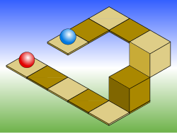
An example of the limitations of isometric projection. The height difference between the red and blue balls cannot be determined locally.
Impossible staircase.svg
The Penrose stairs depicts a staircase which seems to ascend (anticlockwise) or descend (clockwise) yet forms a continuous loop.

As with all types of parallel projection, objects drawn with isometric projection do not appear larger or smaller as they extend closer to or away from the viewer. While advantageous for architectural drawings where measurements need to be taken directly, the result is a perceived distortion, as unlike perspective projection, it is not how human vision or photography normally work. It also can easily result in situations where depth and altitude are difficult to gauge, as is shown in the illustration to the right or above. This can appear to create paradoxical or impossible shapes, such as the Penrose stairs.

Usage in video games and pixel art

Isometric video game graphics are graphics employed in video games and pixel art that utilize a parallel projection, but which angle the viewpoint to reveal facets of the environment that would otherwise not be visible from a top-down perspective or side view, thereby producing a three-dimensional effect. Despite the name, isometric computer graphics are not necessarily truly isometrici.e., the x, y, and z axes are not necessarily oriented 120° to each other. Instead, a variety of angles are used, with dimetric projection and a 2:1 pixel ratio being the most common. The terms "34 perspective", "34 view", "2.5D", and "pseudo 3D" are also sometimes used, although these terms can bear slightly different meanings in other contexts.

Once common, isometric projection became less so with the advent of more powerful 3D graphics systems, and as video games began to focus more on action and individual characters. [7] However, video games utilizing isometric projectionespecially computer role-playing games have seen a resurgence in recent years within the indie gaming scene. [7] [8]

See also

Related Research Articles

<span class="mw-page-title-main">Tetrahedron</span> Polyhedron with 4 faces

In geometry, a tetrahedron, also known as a triangular pyramid, is a polyhedron composed of four triangular faces, six straight edges, and four vertex corners. The tetrahedron is the simplest of all the ordinary convex polyhedra.

<span class="mw-page-title-main">Ellipsoid</span> Quadric surface that looks like a deformed sphere

An ellipsoid is a surface that can be obtained from a sphere by deforming it by means of directional scalings, or more generally, of an affine transformation.

In mechanics and geometry, the 3D rotation group, often denoted SO(3), is the group of all rotations about the origin of three-dimensional Euclidean space under the operation of composition.

Unit quaternions, known as versors, provide a convenient mathematical notation for representing spatial orientations and rotations of elements in three dimensional space. Specifically, they encode information about an axis-angle rotation about an arbitrary axis. Rotation and orientation quaternions have applications in computer graphics, computer vision, robotics, navigation, molecular dynamics, flight dynamics, orbital mechanics of satellites, and crystallographic texture analysis.

<span class="mw-page-title-main">3D projection</span> Design technique

A 3D projection is a design technique used to display a three-dimensional (3D) object on a two-dimensional (2D) surface. These projections rely on visual perspective and aspect analysis to project a complex object for viewing capability on a simpler plane.

<span class="mw-page-title-main">Gimbal lock</span> Loss of one degree of freedom in a three-dimensional, three-gimbal mechanism

Gimbal lock is the loss of one degree of freedom in a three-dimensional, three-gimbal mechanism that occurs when the axes of two of the three gimbals are driven into a parallel configuration, "locking" the system into rotation in a degenerate two-dimensional space.

<span class="mw-page-title-main">Euler angles</span> Description of the orientation of a rigid body

The Euler angles are three angles introduced by Leonhard Euler to describe the orientation of a rigid body with respect to a fixed coordinate system.

An infinitesimal rotation matrix or differential rotation matrix is a matrix representing an infinitely small rotation.

<span class="mw-page-title-main">Oblique projection</span> Type of technical drawing

Oblique projection is a simple type of technical drawing of graphical projection used for producing two-dimensional (2D) images of three-dimensional (3D) objects.

In numerical linear algebra, a Givens rotation is a rotation in the plane spanned by two coordinates axes. Givens rotations are named after Wallace Givens, who introduced them to numerical analysts in the 1950s while he was working at Argonne National Laboratory.

In linear algebra, linear transformations can be represented by matrices. If is a linear transformation mapping to and is a column vector with entries, then

In linear algebra, a rotation matrix is a transformation matrix that is used to perform a rotation in Euclidean space. For example, using the convention below, the matrix

<span class="mw-page-title-main">Euler's rotation theorem</span> Movement with a fixed point is rotation

In geometry, Euler's rotation theorem states that, in three-dimensional space, any displacement of a rigid body such that a point on the rigid body remains fixed, is equivalent to a single rotation about some axis that runs through the fixed point. It also means that the composition of two rotations is also a rotation. Therefore the set of rotations has a group structure, known as a rotation group.

Spatial rotations in three dimensions can be parametrized using both Euler angles and unit quaternions. This article explains how to convert between the two representations. Actually this simple use of "quaternions" was first presented by Euler some seventy years earlier than Hamilton to solve the problem of magic squares. For this reason the dynamics community commonly refers to quaternions in this application as "Euler parameters".

<span class="mw-page-title-main">Rotation of axes in two dimensions</span> Transformation of coordinates through an angle

In mathematics, a rotation of axes in two dimensions is a mapping from an xy-Cartesian coordinate system to an x′y′-Cartesian coordinate system in which the origin is kept fixed and the x′ and y′ axes are obtained by rotating the x and y axes counterclockwise through an angle . A point P has coordinates (x, y) with respect to the original system and coordinates (x′, y′) with respect to the new system. In the new coordinate system, the point P will appear to have been rotated in the opposite direction, that is, clockwise through the angle . A rotation of axes in more than two dimensions is defined similarly. A rotation of axes is a linear map and a rigid transformation.

In geometry, various formalisms exist to express a rotation in three dimensions as a mathematical transformation. In physics, this concept is applied to classical mechanics where rotational kinematics is the science of quantitative description of a purely rotational motion. The orientation of an object at a given instant is described with the same tools, as it is defined as an imaginary rotation from a reference placement in space, rather than an actually observed rotation from a previous placement in space.

<span class="mw-page-title-main">Dual quaternion</span>

In mathematics, the dual quaternions are an 8-dimensional real algebra isomorphic to the tensor product of the quaternions and the dual numbers. Thus, they may be constructed in the same way as the quaternions, except using dual numbers instead of real numbers as coefficients. A dual quaternion can be represented in the form A + εB, where A and B are ordinary quaternions and ε is the dual unit, which satisfies ε2 = 0 and commutes with every element of the algebra. Unlike quaternions, the dual quaternions do not form a division algebra.

The direct-quadrature-zerotransformation or zero-direct-quadraturetransformation is a tensor that rotates the reference frame of a three-element vector or a three-by-three element matrix in an effort to simplify analysis. The DQZ transform is the product of the Clarke transform and the Park transform, first proposed in 1929 by Robert H. Park.

In physics and engineering, Davenport chained rotations are three chained intrinsic rotations about body-fixed specific axes. Euler rotations and Tait–Bryan rotations are particular cases of the Davenport general rotation decomposition. The angles of rotation are called Davenport angles because the general problem of decomposing a rotation in a sequence of three was studied first by Paul B. Davenport.

<span class="mw-page-title-main">Axonometry</span> The process of projecting a three-dimensional object onto a two-dimmensional plane

Axonometry is a graphical procedure belonging to descriptive geometry that generates a planar image of a three-dimensional object. The term "axonometry" means "to measure along axes", and indicates that the dimensions and scaling of the coordinate axes play a crucial role. The result of an axonometric procedure is a uniformly-scaled parallel projection of the object. In general, the resulting parallel projection is oblique ; but in special cases the result is orthographic, which in this context is called an orthogonal axonometry.

References

  1. Ingrid Carlbom; Joseph Paciorek; Dan Lim (December 1978). "Planar Geometric Projections and Viewing Transformations". ACM Computing Surveys . 10 (4): 465–502. CiteSeerX   10.1.1.532.4774 . doi:10.1145/356744.356750. S2CID   708008.
  2. William Farish (1822) "On Isometrical Perspective". In: Cambridge Philosophical Transactions. 1 (1822).
  3. Barclay G. Jones (1986). Protecting historic architecture and museum collections from natural disasters. University of Michigan. ISBN   0-409-90035-4. p.243.
  4. Charles Edmund Moorhouse (1974). Visual messages: graphic communication for senior students.
  5. J. Krikke (1996). "A Chinese perspective for cyberspace? Archived 2016-02-05 at the Wayback Machine ". In: International Institute for Asian Studies Newsletter, 9, Summer 1996.
  6. 1 2 Jan Krikke (2000). "Axonometry: a matter of perspective". In: Computer Graphics and Applications, IEEE Jul/Aug 2000. Vol 20 (4), pp. 7–11.
  7. 1 2 Signor, Jeremy (2014-12-19). "Retronauts: The Continued Relevance of Isometric Games". usgamer.net. Gamer Network. Archived from the original on 2022-09-25. Retrieved 2017-04-01.
  8. Vas, Gergo (2013-03-18). "The Best-Looking Isometric Games". kotaku.com. Gizmodo Media Group. Archived from the original on 2021-10-10. Retrieved 2017-04-01.