Parallel projection terminology and notations. The two blue parallel line segments to the right remain parallel when projected onto the image plane to the left.
A parallel projection is a particular case of projection in mathematics and graphical projection in technical drawing. Parallel projections can be seen as the limit of a central or perspective projection, in which the rays pass through a fixed point called the center or viewpoint, as this point is moved towards infinity. Put differently, a parallel projection corresponds to a perspective projection with an infinite focal length (the distance between the lens and the focal point in photography) or "zoom". Further, in parallel projections, lines that are parallel in three-dimensional space remain parallel in the two-dimensionally projected image.
A perspective projection of an object is often considered more realistic than a parallel projection, since it more closely resembles human vision and photography. However, parallel projections are popular in technical applications, since the parallelism of an object's lines and faces is preserved, and direct measurements can be taken from the image. Among parallel projections, orthographic projections are seen as the most realistic, and are commonly used by engineers. On the other hand, certain types of oblique projections (for instance cavalier projection, military projection) are very simple to implement, and are used to create quick and informal pictorials of objects.
The term parallel projection is used in the literature to describe both the procedure itself (a mathematical mapping function) as well as the resulting image produced by the procedure.
Properties
Two parallel projections of a cube. In an orthographic projection (at left), the projection lines are perpendicular to the image plane (pink). In an oblique projection (at right), the projection lines are at a skew angle to the image plane.
Every parallel projection has the following properties:
It is uniquely defined by its projection plane Π and the direction of the (parallel) projection lines. The direction must not be parallel to the projection plane.
Any point of the space has a unique image in the projection plane Π, and the points of Π are fixed.
Any line not parallel to direction is mapped onto a line; any line parallel to is mapped onto a point.
Parallel lines are mapped on parallel lines (or on a pair of points if they are parallel to ).
The ratio of the lengths of two line segments on a line or on two parallel lines stays unchanged.[1] As a special case, midpoints are mapped on midpoints.
The centroid of a set of points in space is mapped to the centroid of the image of those points
The length of a line segment parallel to the projection plane remains unchanged. The length of any line segment is not increased if the projection is orthographic.
Any circle that lies in a plane parallel to the projection plane is mapped onto a circle with the same radius. Any other circle is mapped onto an ellipse (or a line segment if direction is parallel to the circle's plane).
Angles in general are not preserved. But right angles with one line parallel to the projection plane remain unchanged.
Any rectangle is mapped onto a parallelogram (or a line segment if is parallel to the rectangle's plane).
Any figure in a plane that is parallel to the image plane is congruent to its image.
Types
Classification of Parallel projection and some 3D projectionsA parallel projection corresponds to a perspective projection with a hypothetical viewpoint; i.e. one where the camera lies an infinite distance away from the object and has an infinite focal length, or "zoom".Various projections and how they are produced
Orthographic projection is derived from the principles of descriptive geometry, and is a type of parallel projection where the projection rays are perpendicular to the projection plane. It is the projection type of choice for working drawings. The term orthographic is sometimes reserved specifically for depictions of objects where the principal axes or planes of the object are also parallel with the projection plane (or the paper on which the orthographic or parallel projection is drawn). However, the term primary view is also used. In multiview projections, up to six pictures of an object are produced, with each projection plane perpendicular to one of the coordinate axes. However, when the principal planes or axes of an object are not parallel with the projection plane, but are rather tilted to some degree to reveal multiple sides of the object, they are called auxiliary views or pictorials. Sometimes, the term axonometric projection is reserved solely for these views, and is juxtaposed with the term orthographic projection. But axonometric projection might be more accurately described as being synonymous with parallel projection, and orthographic projection a type of axonometric projection.
The primary views include plans, elevations and sections; and the isometric, dimetric and trimetric projections could be considered auxiliary views. A typical (but non-obligatory) characteristic of multiview orthographic projections is that one axis of space usually is displayed as vertical.
When the viewing direction is perpendicular to the surface of the depicted object, regardless of the object's orientation, it is referred to as a normal projection. Thus, in the case of a cube oriented with a space's coordinate system, the primary views of the cube would be considered normal projections.
Comparison of several types of graphical projection. The presence of one or more 90° principal angles is usually a good indication that the perspective is oblique.
In an oblique projection, the parallel projection rays are not perpendicular to the viewing plane, but strike the projection plane at an angle other than ninety degrees.[2] In both orthographic and oblique projection, parallel lines in space appear parallel on the projected image. Because of its simplicity, oblique projection is used exclusively for pictorial purposes rather than for formal, working drawings. In an oblique pictorial drawing, the displayed angles separating the coordinate axes as well as the foreshortening factors (scaling) are arbitrary. The distortion created thereby is usually attenuated by aligning one plane of the imaged object to be parallel with the plane of projection, creating a truly-formed, full-size image of the chosen plane. Special types of oblique projections include military, cavalier and cabinet projection.[3]
Analytic representation
If the image plane is given by equation and the direction of projection by , then the projection line through the point is parametrized by
with .
The image of is the intersection of line with plane ; it is given by the equation
In several cases, these formulas can be simplified.
(S1) If one can choose the vectors and such that , the formula for the image simplifies to
(S2) In an orthographic projection, the vectors and are parallel. In this case, one can choose and one gets
(S3) If one can choose the vectors and such that , and if the image plane contains the origin, one has and the parallel projection is a linear mapping:
From this analytic representation of a parallel projection one can deduce most of the properties stated in the previous sections.
History
Axonometry originated in China.[4][unreliable source?] Its function in Chinese art was unlike the linear perspective in European art since its perspective was not objective, or looking from the outside. Instead, its patterns used parallel projections within the painting that allowed the viewer to consider both the space and the ongoing progression of time in one scroll.[5] According to science author and Medium journalist Jan Krikke, axonometry, and the pictorial grammar that goes with it, had taken on a new significance with the introduction of visual computing andengineering drawing.[5][4][6][7]
The concept of isometry had existed in a rough empirical form for centuries, well before Professor William Farish (1759–1837) of Cambridge University was the first to provide detailed rules for isometric drawing.[8][9]
Farish published his ideas in the 1822 paper "On Isometric Perspective", in which he recognized the "need for accurate technical working drawings free of optical distortion. This would lead him to formulate isometry. Isometry means "equal measures" because the same scale is used for height, width, and depth".[10]
From the middle of the 19th century, according to Jan Krikke (2006)[10] isometry became an "invaluable tool for engineers, and soon thereafter axonometry and isometry were incorporated in the curriculum of architectural training courses in Europe and the U.S. The popular acceptance of axonometry came in the 1920s, when modernist architects from the Bauhaus and De Stijl embraced it".[10] De Stijl architects like Theo van Doesburg used axonometry for their architectural designs, which caused a sensation when exhibited in Paris in 1923".[10]
Since the 1920s axonometry, or parallel perspective, has provided an important graphic technique for artists, architects, and engineers. Like linear perspective, axonometry helps depict three-dimensional space on a two-dimensional picture plane. It usually comes as a standard feature of CAD systems and other visual computing tools.[5]
Optical-grinding engine model (1822), drawn in 30° isometric perspective[11]
Example of a dimetric perspective drawing from a US Patent (1874)
Example of dimetric projection in Chinese art in an illustrated edition of the Romance of the Three Kingdoms, China, c. 15th century CE.
Detail of the original version of Along the River During the Qingming Festival attributed to Zhang Zeduan (1085–1145). Note that the picture switches back and forth between axonometric and perspective projection in different parts of the image, and is thus inconsistent.
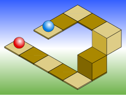
In this drawing, the blue sphere is two units higher than the red one. However, this difference in elevation is not apparent if one covers the right half of the picture.
The Penrose stairs depicts a staircase which seems to ascend (anticlockwise) or descend (clockwise) yet forms a continuous loop.
Paul Kuniholm Mural 1924-1st-Ave-Created-2019-July-6
Objects drawn with parallel projection do not appear larger or smaller as they lie closer to or farther away from the viewer. While advantageous for architectural drawings, where measurements must be taken directly from the image, the result is a perceived distortion, since unlike perspective projection, this is not how human vision or photography normally works. It also can easily result in situations where depth and altitude are difficult to gauge, as is shown in the illustration to the right.
This visual ambiguity has been exploited in op art, as well as "impossible object" drawings. Though not strictly parallel, M. C. Escher's Waterfall (1961) is a well-known image, in which a channel of water seems to travel unaided along a downward path, only to then paradoxically fall once again as it returns to its source. The water thus appears to disobey the law of conservation of energy. Oscar Reutersvard is credited with discovery of the impossible object, an example of the impossible triangle (top) shown in this mural by Paul Kuniholm.
↑Barclay G. Jones (1986). Protecting historic architecture and museum collections from natural disasters. University of Michigan. ISBN0-409-90035-4. p.243.
↑Charles Edmund Moorhouse (1974). Visual messages: graphic communication for senior students.
This page is based on this Wikipedia article Text is available under the CC BY-SA 4.0 license; additional terms may apply. Images, videos and audio are available under their respective licenses.