Generally, line-level signals sit in the middle of the hierarchy of signal levels in audio engineering. There are weaker signals, such as those from microphones (Mic Level/Microphone Level) and instrument pickups (Instrument Level), and stronger signals, such as those used to drive headphones and loudspeakers (Speaker Level). The "strength" of these various signals does not necessarily refer to the output voltage of the source device; it also depends on its output impedance and output power capability.
Consumer electronic devices concerned with audio (for example, sound cards) often have a connector labeled line in and/or line out. Line out provides an audio signal output and line in receives a signal input. The line in/out connections on consumer-oriented audio equipment are typically unbalanced, with a 3.5 mm (0.14inch, but commonly called eighth inch) 3-conductor TRS minijack connector providing ground, left channel, and right channel, or stereo RCA jacks. Professional equipment commonly uses balanced connections on 6.35 mm (1/4inch) TRS phone jacks or XLR connectors. Professional equipment may also use unbalanced connections with (1/4inch) TS phone jacks.
Nominal levels
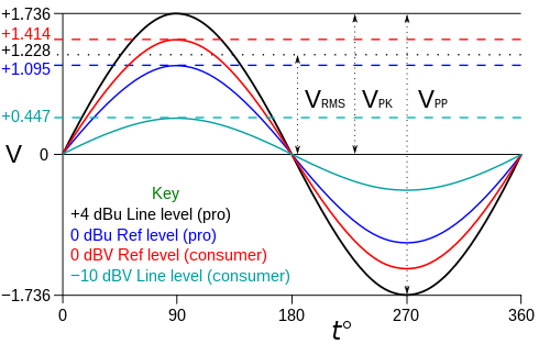
Voltage vs. time of sine waves at reference and line levels, with VRMS, VPK, and VPP marked for the +4dBu line level.
A line level describes a line's nominal signal level as a ratio, expressed in decibels, against a standard reference voltage. The nominal level and the reference voltage against which it is expressed depend on the line level being used. While the nominal levels themselves vary, only two reference voltages are common: decibel volts (dBV) for consumer applications, and decibels unloaded (dBu) for professional applications.
The decibel volt reference voltage is 1 VRMS = 0 dBV.[1] The decibel unloaded reference voltage, 0 dBu, is the AC voltage required to produce 1 mW of power across a 600 Ω impedance (approximately 0.7746 VRMS).[2] This awkward unit is a holdover from the early telephone standards, which used 600Ω sources and loads, and measured dissipated power in decibel-milliwatts (dBm). Modern audio equipment does not use 600Ω matched loads, hence dBm unloaded (dBu).
The most common nominal level for professional equipment is +4 dBu (by convention, decibel values are written with an explicit sign symbol). For consumer equipment it is −10 dBV, which is used to reduce manufacturing costs.[3]
Expressed in absolute terms, a signal at −10 dBV is equivalent to a sine wave signal with a peak amplitude (VPK) of approximately 0.447 volts, or any general signal at 0.316 voltsroot mean square (VRMS). A signal at +4 dBu is equivalent to a sine wave signal with a peak amplitude of approximately 1.736 volts, or any general signal at approximately 1.228VRMS.
Peak-to-peak (sometimes abbreviated as p-p) amplitude (VPP) refers to the total voltage swing of a signal, which is double the peak amplitude of the signal. For instance, a signal with a peak amplitude of ±0.5 V has a p-p amplitude of 1.0 V.
Line levels and their approximate nominal voltage levels
Use
Nominal level
Nominal level, VRMS
Peak amplitude, VPK
Peak-to-peak amplitude, VPP
Professional audio
+4 dBu
1.228
1.736
3.472
Consumer audio
−10 dBV
0.316
0.447
0.894
The line level signal is an alternating current signal without a DC offset, meaning that its voltage varies with respect to signal ground from the peak amplitude (for example +1.5 V) to the equivalent negative voltage (−1.5 V).[4]
Impedances
As cables between line output and line input are generally extremely short compared to the audio signal wavelength in the cable, transmission line effects can be disregarded and impedance matching need not be used. Instead, line level circuits use the impedance bridging principle, in which a low impedance output drives a high impedance input. A typical line out connection has an output impedance from 100 to 600 Ω, with lower values being more common in newer equipment. Line inputs present a much higher impedance, typically 10 kΩ or more.[5]
The two impedances form a voltage divider with a shunt element that is large relative to the size of the series element, which ensures that little of the signal is shunted to ground and that current requirements are minimized. Most of the voltage asserted by the output appears across the input impedance and almost none of the voltage is dropped across the output.[5] The line input acts similarly to a high impedance voltmeter or oscilloscope input, measuring the voltage asserted by the output while drawing minimal current (and hence minimal power) from the source. The high impedance of the line in circuit does not load down the output of the source device.
These are voltage signals (as opposed to current signals) and it is the signal information (voltage) that is desired, not power to drive a transducer, such as a speaker or antenna. The actual information that is exchanged between the devices is the variance in voltage; it is this alternating voltage signal that conveys the information, making the current irrelevant.
Line outputs usually present a source impedance of from 100 to 600 ohms. The voltage can reach 2 volts peak-to-peak with levels referenced to −10 dBV (300 mV) at 10 kΩ. The frequency response of most modern equipment is advertised as at least 20Hz to 20kHz, which corresponds to the range of human hearing. Line outputs are intended to drive a load impedance of 10,000 ohms; with only a few volts, this requires only minimal current.
Connecting other devices
Connecting a low-impedance load such as a loudspeaker (usually 4 to 8 Ω) to a line out will essentially short circuit the output circuit. Such loads are around 1/1000 the impedance a line out is designed to drive, so the line out is usually not designed to source the current that would be drawn by a 4 to 8 ohm load at normal line out signal voltages. The result will be very weak sound from the speaker and possibly a damaged line-out circuit.
Headphone outputs and line outputs are sometimes confused. Different make and model headphones have widely varying impedances, from as little as 20 Ω to a few hundred ohms; the lowest of these will have results similar to a speaker, while the highest may work acceptably if the line out impedance is low enough and the headphones are sensitive enough.
Conversely, a headphone output generally has a source impedance of only a few ohms (to provide a bridging connection with 32-ohm headphones) and will easily drive a line input.
For similar reasons, wye-cables (or Y-splitters) should not be used to combine two line-out signals into a single line in. Each line output would be driving the other line output as well as the intended input, again resulting in a much heavier load than designed for. This will result in signal loss and possibly even damage. An active mixer, using for example op-amps, should be used instead.[6] A large resistor in series with each output can be used to safely mix them together, but must be appropriately designed for the load impedance and cable length.
It is intended by designers that the line out of one device be connected to the line input of another. Line inputs are designed to accept voltage levels in the range provided by line outputs. Impedances, on the other hand, are deliberately not matched from output to input. The impedance of a line input is typically around 10 kΩ. When driven by a line output's usual low impedance of 100 to 600 ohms, this forms a "bridging" connection in which most of the voltage generated by the source (the output) is dropped across the load (the input), and minimal current flows due to the load's relatively high impedance.
Although line inputs have a high impedance compared to that of line outputs, they should not be confused with so-called "Hi-Z" inputs (Z being the symbol for impedance) which have an impedance of 47 kΩ to over 1 MΩ. These "Hi-Z" or "instrument" inputs generally have higher gain than a line input. They are designed to be used with, for example, electric guitar pickups and "direct injection" boxes. Some of these sources can provide only minimal voltage and current and the high-impedance input is designed not to load them excessively.
Line level in traditional signal paths
Acoustic sounds (such as voices or musical instruments) are often recorded with transducers (microphones and pickups) that produce weak electrical signals. These signals must be amplified to line level, where they are more easily manipulated by other devices such as mixing consoles and tape recorders. Such amplification is performed by a device known as a preamplifier or "preamp", which boosts the signal to line level. After manipulation at line level, signals are then typically sent to a power amplifier, where they are amplified to levels that can drive headphones or loudspeakers. These convert the signals back into sounds that can be heard through the air.
Most phonograph cartridges also have a low output level and require a preamp; typically, a home stereo integrated amplifier or receiver will have a special phono input. This input passes the signal through a phono preamp, which applies RIAA equalization to the signal as well as boosting it to line level.
12Dennis Bohn (May 1996). "Practical Line-Driving Current Requirements". RaneNotes. Rane Corporation. Retrieved 2025-09-01. Practically speaking, electrical engineering transmission line theory does not apply to real world audio lines. ... This paves the way for simple R-C modeling of our audio line.
↑Dennis Bohn (April 2004). "Why Not Wye?". RaneNotes. Rane Corporation. Retrieved 2025-09-01. Outputs are low impedance and must only be connected to high impedance inputs -- never, never tie two outputs directly together -- never. If you do, then each output tries to drive the very low impedance of the other, forcing both outputs into current-limit and possible damage. As a minimum, severe signal loss results.
This page is based on this Wikipedia article Text is available under the CC BY-SA 4.0 license; additional terms may apply. Images, videos and audio are available under their respective licenses.