Mm'-type filter

Last updated

mm'-type filters, also called double-m-derived filters, are a type of electronic filter designed using the image method. They were patented by Otto Zobel in 1932. [1] Like the m-type filter from which it is derived, the mm'-type filter type was intended to provide an improved impedance match into the filter termination impedances and originally arose in connection with telephone frequency division multiplexing. The filter has a similar transfer function to the m-type, having the same advantage of rapid cut-off, but the input impedance remains much more nearly constant if suitable parameters are chosen. In fact, the cut-off performance is better for the mm'-type if like-for-like impedance matching are compared rather than like-for-like transfer function. It also has the same drawback of a rising response in the stopband as the m-type. However, its main disadvantage is its much increased complexity which is the chief reason its use never became widespread. It was only ever intended to be used as the end sections of composite filters, the rest of the filter being made up of other sections such as k-type and m-type sections.

Contents

An incidental advantage of the mm'-type is that it has two independent parameters (m and m') that the designer can adjust. This allows for two different design criteria to be independently optimised.

Parts of this article or section rely on the reader's knowledge of the complex impedance representation of capacitors and inductors and on knowledge of the frequency domain representation of signals.

Background

The mm'-type filter was an extension of Zobel's previous m-type filter, which itself grew out of George Campbell's k-type design. Zobel's m-type is arrived at by applying the m-derivation process (see m-derived filter) to the k-type filter. Completely analogously, the mm'-type is arrived at by applying the m-derived process to the m-type filter. The value of m used in the second transformation is designated m' to distinguish it from m, hence the naming of the filter mm'-type. However, this filter is not a member of the class of filters, general mn-type image filters, which are a generalisation of m-type filters. Rather, it is a double application of the m-derived process and for those filters the arbitrary parameters are usually designated m1, m2, m3 etc., rather than m, m', m'' as here.

The importance of the filter lies in its impedance properties. Some of the impedance terms and section terms used in image design theory are pictured in the diagram below. As always, image theory defines quantities in terms of an infinite cascade of two-port sections, and in the case of the filters being discussed, an infinite ladder network of L-sections.

Image filter terms.svg

The sections of the hypothetical infinite filter are made up of series impedance elements of 2Z and shunt admittance elements of 2Y. The factor of two is introduced since it is normal to work in terms of half-sections where it disappears. The image impedance of the input and output port of a section, Zi1 and Zi2, will generally not be the same. However, for a mid-series section (that is, a section from halfway through a series element to halfway through the next series element) will have the same image impedance on both ports due to symmetry. This image impedance is designated ZiT due to the "T" topology of a mid-series section. Likewise, the image impedance of a mid-shunt section is designated Z due to the "Π" topology. Half of such a "T" or "Π" section is (unsurprisingly) called a half-section. The image impedances of the half section are dissimilar on the input and output ports but are equal to the mid-series ZiT on the side presenting the series element and the mid-shunt Z on the side presenting the shunt element.

A mid-series derived section (that is, a series m-type filter) has precisely the same image impedance, ZiT, as a k-type mid-series "T" filter. However, the image impedance of a half-section of such a filter (on the shunt side) is not the same and is designated ZiΠm. Similarly, the series element side of a shunt m-derived filter half-section is designated ZiTm.

Derivation

Derivation of a mm'-type mid-shunt filter section. Starting from a prototype constant k filter T-filter, the circuit is transformed to a m-type mid-series derived filter, re-implemented as P-section, transformed again to a mid-shunt derived mm'-type. Mm' filter derivation.svg
Derivation of a mm'-type mid-shunt filter section. Starting from a prototype constant k filter T-filter, the circuit is transformed to a m-type mid-series derived filter, re-implemented as Π-section, transformed again to a mid-shunt derived mm'-type.

The m-derived process starts with a k-type filter midsection and transforms it into a m-derived filter with a different transfer function but retaining the same image impedance and passband. Two different results are obtained depending on whether the process began with a T-section or a Π-section. From a T-section, the series Z and shunt Y are multiplied by an arbitrary parameter m(0 < m < 1). An additional impedance is then inserted in series with Y whose value is that which restores the original image impedance. The half-sections resulting from splitting the T-section, however, will show a different image impedance at the split, ZiΠm. Two such half-sections cascaded with the ZiT impedances facing, will form a Π-section with image impedance ZiΠm. The m-derived process can now be applied to this new section, but with a new parameter m'. The series Z and shunt Y are multiplied by m' and an additional admittance is inserted in parallel with the series elements to bring the image impedance back to its original value of ZiΠm. Again, the half sections will have a different image impedance at the split ports and this is designated ZiTmm'.

The dual realisation of this filter is obtained in a completely analogous way by first transforming a mid-shunt k-type Π-section, forming the resulting mid-series m-type T-section and then transforming using m', resulting in a new Π flavour of Zimm', ZiΠmm', which is the dual of ZiTmm'.

The m-derivation transformation can, in principle, be applied ad-infinitum and produce mm'm''-types etc. There is, however, no practical benefit in doing this. The improvements obtained diminish at each iteration and are not worth the increase in complexity. Note that applying the m-derived transformation twice to a T-section (or Π-section) will merely result in an m-type filter with a different value of m. The transformation must be applied alternately to T-sections and Π-sections for a completely new form of filter to be obtained.

mm'-type low-pass filter series half section. C = L/R0 Mm'-Derived Series Low-pass Filter Half-section.svg
mm'-type low-pass filter series half section. C = L/R0

Operating frequency

For a low-pass prototype, the cut-off frequency is given by the same expression as for the m-type and the k-type;

The pole of attenuation occurs at;

Image impedance

See also Image impedance#Derivation
Image impedance plot of an optimised mm'-type shunt section (ZiTmm', in blue) compared with an m-derived prototype shunt image impedance (ZiTm, in red) for m = 0.6. A constant-k filter's image impedance is also shown (ZiT, in green). Mm'-Derived Low-pass Image Impedance.svg
Image impedance plot of an optimised mm'-type shunt section (ZiTmm', in blue) compared with an m-derived prototype shunt image impedance (ZiTm, in red) for m = 0.6. A constant-k filter's image impedance is also shown (ZiT, in green).

The following expressions for image impedances are all referenced to the low-pass prototype section. They are scaled to the nominal impedance R0 = 1 and the frequencies in those expressions are all scaled to the cut-off frequency ωc = 1.

"T" port image impedance

The image impedance looking into a "T" topology port of a shunt derived section is given by,

For comparison;

  and  

"Π" port image impedance

The image impedance looking into a "Π" topology port of a series derived section is given by,

For comparison;

  and  

Optimisation

Note that can be adjusted independently of m by adjusting m'. It is therefore possible to adjust the impedance characteristic and frequency response characteristic independently. However, for optimum impedance match it is necessary to adjust both parameters solely for maximally flat image resistance in the passband. The term resistance is used because the image impedance is purely real in the passband between cut-off frequencies and purely imaginary outside the passband. It is not possible to obtain an exact impedance match across the entire band. With two degrees of freedom it is only possible to match the impedance exactly at two spot frequencies. It has been determined empirically [1] that a good match is made with the values;

This amounts to setting the match to be exact at frequencies 0.8062 and 0.9487 rad/s for the prototype filter and the impedance departs less than 2% from nominal from 0 to 0.96 rad/s, that is, nearly all of the passband.

The transfer function of an mm'-type is the same as an m-type with m set to the product mm' and in this case mm'=0.3. Where an m-type section is used for impedance matching the optimum value of m is m=0.6. Steepness of cut-off increases with decreasing m so an mm'-type section has this as an incidental advantage over an m-type in this application.

Transmission parameters

mm'-type low-pass filter transfer function for a single half-section with various values of mm'

g
=
a
+
i
b
{\displaystyle \gamma =\alpha +i\beta \,} Mm'-Type Low-pass Transfer Function (1 Half-section).svg
mm'-type low-pass filter transfer function for a single half-section with various values of mm'
    
See also Image impedance#Transfer function

The operating frequencies, transmission parameters and transfer function are identical to those for the m-type and details can be found in that article if the parameter m is replaced by the product mm'. Only the image impedance is different in the mm'-type filter in terms of black box behaviour.

Prototype transformations

The plots shown of image impedance and attenuation are the plots of a low-pass prototype filter section. The prototype has a cut-off frequency of ωc=1 rad/s and a nominal impedance R0=1Ω. This is produced by a filter half-section where L=1 henry and C=1 farad. This prototype can be impedance scaled and frequency scaled to the desired values. The low-pass prototype can also be transformed into high-pass, band-pass or band-stop types by application of suitable frequency transformations.

Cascading sections

As with all image filters, it is required to match each section into a section of identical image impedance if the theoretical filter response is to be achieved. This is a particular difficulty for the end sections of the filter which are often working into resistive terminations which cannot be matched exactly by an image impedance. Hence the use of the mm'-type as end sections for the filter because of its nearly flat impedance with frequency characteristic in the passband. However, it is not desirable to use it throughout the entire filter. The workhorse of image filters are the k-type sections and these will usually be required somewhere in the filter for good rejection in the stopband well away from cut-off and also because they are the simplest topology and lowest component count. Unfortunately, neither side of a mm'-type can match into a k-type. The solution is to form a composite section from a mm'-type half-section and a m-type section which will match each other on one side if m has the same value for both half-sections. This can, for instance, produce a composite T-section with ZiTmm' facing the termination and ZiT facing the rest of the filter. The T-section will be matched internally with ZiTm. This has the additional incidental advantage of producing two poles of attenuation in the stopband at different frequencies. This is a consequence of m and mm' necessarily being different values.

Image filter sections
 
Unbalanced
L Half sectionT SectionΠ Section
Image Filter L Half-section.svg
Image filter T Section.svg
Image filter Pi Section.svg
Ladder network
Image Filter Ladder Network (Unbalanced).svg
 
Balanced
C Half-sectionH SectionBox Section
Image Filter C Half-section.svg
Image Filter H Section.svg
Image Filter Box Section.svg
Ladder network
Image Filter Ladder Network (Balanced).svg
X Section (mid-T-Derived)X Section (mid-Π-Derived)
Image filter X Section.svg
Image filter X Section (Pi-Derived).svg
N.B.Textbooks and design drawings usually show the unbalanced implementations, but in telecoms it is often required to convert the design to the balanced implementation when used with balanced lines. edit

See also

Related Research Articles

Cutoff frequency Frequency response boundary

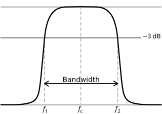
In physics and electrical engineering, a cutoff frequency, corner frequency, or break frequency is a boundary in a system's frequency response at which energy flowing through the system begins to be reduced rather than passing through.

Chebyshev filters are analog or digital filters having a steeper roll-off than Butterworth filters, and have passband ripple or stopband ripple. Chebyshev filters have the property that they minimize the error between the idealized and the actual filter characteristic over the range of the filter, but with ripples in the passband. This type of filter is named after Pafnuty Chebyshev because its mathematical characteristics are derived from Chebyshev polynomials. Type I Chebyshev filters are usually referred to as "Chebyshev filters", while type II filters are usually called "inverse Chebyshev filters".

Butterworth filter Type of signal processing filter

The Butterworth filter is a type of signal processing filter designed to have a frequency response that is as flat as possible in the passband. It is also referred to as a maximally flat magnitude filter. It was first described in 1930 by the British engineer and physicist Stephen Butterworth in his paper entitled "On the Theory of Filter Amplifiers".

An elliptic filter is a signal processing filter with equalized ripple (equiripple) behavior in both the passband and the stopband. The amount of ripple in each band is independently adjustable, and no other filter of equal order can have a faster transition in gain between the passband and the stopband, for the given values of ripple. Alternatively, one may give up the ability to adjust independently the passband and stopband ripple, and instead design a filter which is maximally insensitive to component variations.

Stub (electronics) Short electrical transmission line

In microwave and radio-frequency engineering, a stub or resonant stub is a length of transmission line or waveguide that is connected at one end only. The free end of the stub is either left open-circuit, or short-circuited. Neglecting transmission line losses, the input impedance of the stub is purely reactive; either capacitive or inductive, depending on the electrical length of the stub, and on whether it is open or short circuit. Stubs may thus function as capacitors, inductors and resonant circuits at radio frequencies.

Ripple in electronics is the residual periodic variation of the DC voltage within a power supply which has been derived from an alternating current (AC) source. This ripple is due to incomplete suppression of the alternating waveform after rectification. Ripple voltage originates as the output of a rectifier or from generation and commutation of DC power.

The telegrapher's equations are a pair of coupled, linear partial differential equations that describe the voltage and current on an electrical transmission line with distance and time. The equations come from Oliver Heaviside who developed the transmission line model starting with an August 1876 paper, On the Extra Current. The model demonstrates that the electromagnetic waves can be reflected on the wire, and that wave patterns can form along the line.

Electronic filter topology Electronic filter circuits defined by component connection

Electronic filter topology defines electronic filter circuits without taking note of the values of the components used but only the manner in which those components are connected.

Zobel network

Zobel networks are a type of filter section based on the image-impedance design principle. They are named after Otto Zobel of Bell Labs, who published a much-referenced paper on image filters in 1923. The distinguishing feature of Zobel networks is that the input impedance is fixed in the design independently of the transfer function. This characteristic is achieved at the expense of a much higher component count compared to other types of filter sections. The impedance would normally be specified to be constant and purely resistive. For this reason, Zobel networks are also known as constant resistance networks. However, any impedance achievable with discrete components is possible.

Image impedance is a concept used in electronic network design and analysis and most especially in filter design. The term image impedance applies to the impedance seen looking into a port of a network. Usually a two-port network is implied but the concept can be extended to networks with more than two ports. The definition of image impedance for a two-port network is the impedance, Zi 1, seen looking into port 1 when port 2 is terminated with the image impedance, Zi 2, for port 2. In general, the image impedances of ports 1 and 2 will not be equal unless the network is symmetrical with respect to the ports.

Lattice phase equaliser

A lattice phase equaliser or lattice filter is an example of an all-pass filter. That is, the attenuation of the filter is constant at all frequencies but the relative phase between input and output varies with frequency. The lattice filter topology has the particular property of being a constant-resistance network and for this reason is often used in combination with other constant resistance filters such as bridge-T equalisers. The topology of a lattice filter, also called an X-section is identical to bridge topology. The lattice phase equaliser was invented by Otto Zobel. using a filter topology proposed by George Campbell.

Constant k filters, also k-type filters, are a type of electronic filter designed using the image method. They are the original and simplest filters produced by this methodology and consist of a ladder network of identical sections of passive components. Historically, they are the first filters that could approach the ideal filter frequency response to within any prescribed limit with the addition of a sufficient number of sections. However, they are rarely considered for a modern design, the principles behind them having been superseded by other methodologies which are more accurate in their prediction of filter response.

m-derived filters or m-type filters are a type of electronic filter designed using the image method. They were invented by Otto Zobel in the early 1920s. This filter type was originally intended for use with telephone multiplexing and was an improvement on the existing constant k type filter. The main problem being addressed was the need to achieve a better match of the filter into the terminating impedances. In general, all filters designed by the image method fail to give an exact match, but the m-type filter is a big improvement with suitable choice of the parameter m. The m-type filter section has a further advantage in that there is a rapid transition from the cut-off frequency of the pass band to a pole of attenuation just inside the stop band. Despite these advantages, there is a drawback with m-type filters; at frequencies past the pole of attenuation, the response starts to rise again, and m-types have poor stop band rejection. For this reason, filters designed using m-type sections are often designed as composite filters with a mixture of k-type and m-type sections and different values of m at different points to get the optimum performance from both types.

A composite image filter is an electronic filter consisting of multiple image filter sections of two or more different types.

Filters designed using the image impedance methodology suffer from a peculiar flaw in the theory. The predicted characteristics of the filter are calculated assuming that the filter is terminated with its own image impedances at each end. This will not usually be the case; the filter will be terminated with fixed resistances. This causes the filter response to deviate from the theoretical. This article explains how the effects of image filter end terminations can be taken into account.

Prototype filter Template for electronic filter design

Prototype filters are electronic filter designs that are used as a template to produce a modified filter design for a particular application. They are an example of a nondimensionalised design from which the desired filter can be scaled or transformed. They are most often seen in regard to electronic filters and especially linear analogue passive filters. However, in principle, the method can be applied to any kind of linear filter or signal processing, including mechanical, acoustic and optical filters.

General m<sub>n</sub>-type image filter

These filters are electrical wave filters designed using the image method. They are an invention of Otto Zobel at AT&T Corp. They are a generalisation of the m-type filter in that a transform is applied that modifies the transfer function while keeping the image impedance unchanged. For filters that have only one stopband there is no distinction with the m-type filter. However, for a filter that has multiple stopbands, there is the possibility that the form of the transfer function in each stopband can be different. For instance, it may be required to filter one band with the sharpest possible cut-off, but in another to minimise phase distortion while still achieving some attenuation. If the form is identical at each transition from passband to stopband the filter will be the same as an m-type filter. If they are different, then the general case described here pertains.

Primary line constants Parameters of transmission lines

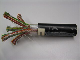
The primary line constants are parameters that describe the characteristics of conductive transmission lines, such as pairs of copper wires, in terms of the physical electrical properties of the line. The primary line constants are only relevant to transmission lines and are to be contrasted with the secondary line constants, which can be derived from them, and are more generally applicable. The secondary line constants can be used, for instance, to compare the characteristics of a waveguide to a copper line, whereas the primary constants have no meaning for a waveguide.

RLC circuit Resistor Inductor Capacitor Circuit

An RLC circuit is an electrical circuit consisting of a resistor (R), an inductor (L), and a capacitor (C), connected in series or in parallel. The name of the circuit is derived from the letters that are used to denote the constituent components of this circuit, where the sequence of the components may vary from RLC.

Frequency selective surface

A frequency-selective surface (FSS) is any thin, repetitive surface designed to reflect, transmit or absorb electromagnetic fields based on the frequency of the field. In this sense, an FSS is a type of optical filter or metal-mesh optical filters in which the filtering is accomplished by virtue of the regular, periodic pattern on the surface of the FSS. Though not explicitly mentioned in the name, FSS's also have properties which vary with incidence angle and polarization as well - these are unavoidable consequences of the way in which FSS's are constructed. Frequency-selective surfaces have been most commonly used in the radio frequency region of the electromagnetic spectrum and find use in applications as diverse as the aforementioned microwave oven, antenna radomes and modern metamaterials. Sometimes frequency selective surfaces are referred to simply as periodic surfaces and are a 2-dimensional analog of the new periodic volumes known as photonic crystals.

References

  1. 1 2 Zobel, O J, Electrical wave filters, US patent 1 850 146, filed 25 Nov 1930, issued 22 Mar 1932
  • Zobel, O. J.,Theory and Design of Uniform and Composite Electric Wave Filters, Bell System Technical Journal, Vol. 2 (1923), pp. 1-46.
  • Mathaei, Young, Jones Microwave Filters, Impedance-Matching Networks, and Coupling Structures McGraw-Hill 1964.
  • Mole, J H, Filter Design Data for Communication Engineers, London: E & F N Spon Ltd.,1952 OCLC   247417663.