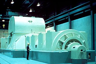
Three-phase electric power is a common method of alternating current electric power generation, transmission, and distribution. It is a type of polyphase system and is the most common method used by electrical grids worldwide to transfer power. It is also used to power large motors and other heavy loads.
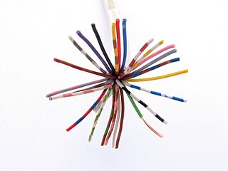
In telecommunications and professional audio, a balanced line or balanced signal pair is a transmission line consisting of two conductors of the same type, each of which have equal impedances along their lengths and equal impedances to ground and to other circuits. The chief advantage of the balanced line format is good rejection of external noise when fed to a differential amplifier. Common forms of balanced line are twin-lead, used for radio frequency signals and twisted pair, used for lower frequencies. They are to be contrasted to unbalanced lines, such as coaxial cable, which is designed to have its return conductor connected to ground, or circuits whose return conductor actually is ground. Balanced and unbalanced circuits can be interconnected using a transformer called a balun.

In electrical engineering, ground or earth is the reference point in an electrical circuit from which voltages are measured, a common return path for electric current, or a direct physical connection to the earth.

Alternating current (AC) is an electric current which periodically reverses direction, in contrast to direct current (DC) which flows only in one direction. Alternating current is the form in which electric power is delivered to businesses and residences, and it is the form of electrical energy that consumers typically use when they plug kitchen appliances, televisions, fans and electric lamps into a wall socket. A common source of DC power is a battery cell in a flashlight. The abbreviations AC and DC are often used to mean simply alternating and direct, as when they modify current or voltage.
Electrical elements are conceptual abstractions representing idealized electrical components, such as resistors, capacitors, and inductors, used in the analysis of electrical networks. All electrical networks can be analyzed as multiple electrical elements interconnected by wires. Where the elements roughly correspond to real components the representation can be in the form of a schematic diagram or circuit diagram. This is called a lumped element circuit model. In other cases infinitesimal elements are used to model the network in a distributed element model.
Balanced audio is a method of interconnecting audio equipment using balanced lines. This type of connection is very important in sound recording and production because it allows the use of long cables while reducing susceptibility to external noise caused by electromagnetic interference.

A balun is an electrical device that converts between a balanced signal and an unbalanced signal. A balun can take many forms and may include devices that also transform impedances but need not do so. Transformer baluns can also be used to connect lines of differing impedance. Sometimes, in the case of transformer baluns, they use magnetic coupling but need not do so. Common-mode chokes are also used as baluns and work by eliminating, rather than ignoring, common mode signals.
In an electrical system, a ground loop or earth loop occurs when two points of a circuit both intended to be at ground reference potential have a potential between them. This can be caused, for example, in a signal circuit referenced to ground, if enough current is flowing in the ground to cause two points to be at different potentials.

Two-phase electrical power was an early 20th-century polyphase alternating current electric power distribution system. Two circuits were used, with voltage phases differing by one-quarter of a cycle, 90°. Usually circuits used four wires, two for each phase. Less frequently, three wires were used, with a common wire with a larger-diameter conductor. Some early two-phase generators had two complete rotor and field assemblies, with windings physically offset to provide two-phase power. The generators at Niagara Falls installed in 1895 were the largest generators in the world at that time and were two-phase machines. Three-phase systems eventually replaced the original two-phase power systems for power transmission and utilization. There remain few two-phase distribution systems, with examples in Philadelphia, Pennsylvania; many buildings in Center City are permanently wired for two-phase and Hartford, Connecticut.
As the neutral point of an electrical supply system is often connected to earth ground, ground and neutral are closely related. Under certain conditions, a conductor used to connect to a system neutral is also used for grounding (earthing) of equipment and structures. Current carried on a grounding conductor can result in objectionable or dangerous voltages appearing on equipment enclosures, so the installation of grounding conductors and neutral conductors is carefully defined in electrical regulations. Where a neutral conductor is used also to connect equipment enclosures to earth, care must be taken that the neutral conductor never rises to a high voltage with respect to local ground.
An autotransformer is an electrical transformer with only one winding. The "auto" prefix refers to the single coil acting alone, not to any kind of automatic mechanism. In an autotransformer, portions of the same winding act as both the primary and secondary sides of the transformer. In contrast, an ordinary transformer has separate primary and secondary windings which are not electrically connected.

A zigzag transformer is a special-purpose transformer with a zigzag or "interconnected star" winding connection, such that each output is the vector sum of two (2) phases offset by 120°. It is used as a grounding transformer, creating a missing neutral connection from an ungrounded 3-phase system to permit the grounding of that neutral to an earth reference point; to perform harmonic mitigation, as they can suppress triplet harmonic currents; to supply 3-phase power as an autotransformer ; and to supply non-standard, phase-shifted, 3-phase power.

A current transformer (CT) is a type of transformer that is used to reduce or multiply an alternating current (AC). It produces a current in its secondary which is proportional to the current in its primary.
In an electrical installation, an earthing system or grounding system connects specific parts of that installation with the Earth's conductive surface for safety and functional purposes. The point of reference is the Earth's conductive surface. The choice of earthing system can affect the safety and electromagnetic compatibility of the installation. Regulations for earthing systems vary considerably among countries, though most follow the recommendations of the International Electrotechnical Commission. Regulations may identify special cases for earthing in mines, in patient care areas, or in hazardous areas of industrial plants.
In electrical engineering, an unbalanced line is a transmission line, often coaxial cable, whose conductors have unequal impedances with respect to ground; as opposed to a balanced line. Microstrip and single-wire lines are also unbalanced lines.
In the design of electrical power systems, the ANSI standard device numbers identifies the features of a protective device such as a relay or circuit breaker. These types of devices protect electrical systems and components from damage when an unwanted event occurs, such as an electrical fault. Device numbers are used to identify the functions of devices shown on a schematic diagram. Function descriptions are given in the standard.
In an electric power system, a fault or fault current is any abnormal electric current. For example, a short circuit is a fault in which current bypasses the normal load. An open-circuit fault occurs if a circuit is interrupted by some failure. In three-phase systems, a fault may involve one or more phases and ground, or may occur only between phases. In a "ground fault" or "earth fault", current flows into the earth. The prospective short-circuit current of a predictable fault can be calculated for most situations. In power systems, protective devices can detect fault conditions and operate circuit breakers and other devices to limit the loss of service due to a failure.

A variety of types of electrical transformer are made for different purposes. Despite their design differences, the various types employ the same basic principle as discovered in 1831 by Michael Faraday, and share several key functional parts.
A balanced circuit is circuitry for use with a balanced line or the balanced line itself. Balanced lines are a common method of transmitting many types of electrical communication signals between two points on two wires. In a balanced line the two signal lines are of a matched impedance to help ensure that interference induced in the line is common-mode and can be removed at the receiving end by circuitry with good common-mode rejection. To maintain the balance, circuit blocks which interface to the line, or are connected in the line, must also be balanced.