Explorer 36

Last updated

Explorer 36
NamesGEOS-2
Geodetic Earth Orbiting Satellite
Mission type Earth science
Operator NASA
COSPAR ID 1968-002A OOjs UI icon edit-ltr-progressive.svg
SATCAT no. 03093
Mission duration2 years (planned)
Spacecraft properties
SpacecraftExplorer XXXVI
Spacecraft typeGeodetic Earth Orbiting Satellite
Bus GEOS
Manufacturer Johns Hopkins University
Applied Physics Laboratory [1]
Launch mass469 kg (1,034 lb)
Start of mission
Launch date11 January 1968, 16:16:10 GMT [2] [3]
Rocket Thor-Delta E1 (Thor 454 / Delta 056)
Launch site Vandenberg, SLC-2E
Contractor Douglas Aircraft Company
Entered service11 January 1968
Orbital parameters
Reference system Geocentric orbit [4]
Regime Low Earth orbit
Perigee altitude 1,082 km (672 mi)
Apogee altitude 1,570 km (980 mi)
Inclination 105.80°
Period 112.20 minutes
Instruments
C-Band Radar Transponder
Laser Tracking Reflector
Magnetometer
NASA Minitrack System
Optical Beacon System
Precipitating Electron Detector
Radio Doppler System
Radio Range/Rate System
SECOR Range Transponder
Explorer program
 

Explorer 36 (also called GEOS 2 or GEOS B, acronym for Geodetic Earth Orbiting Satellite) was a NASA satellite launched as part of the Explorer program, being the second of the two satellites GEOS. Explorer 36 was launched on 11 January 1968 from Vandenberg Air Force Base, with Thor-Delta E1 launch vehicle.

Contents

Explorer 36 was a gravity-gradient stabilized, solar cell powered spacecraft that carried electronic and geodetic instrumentation. The spacecraft's thermal control system was notable for the first non-experimental use of a heat pipe in a spacecraft. [5]

Instruments

The geodetic instrumentation systems included:

Non-geodetic systems included a laser detector and a Minitrack interferometer beacon. The objectives of the spacecraft were to optimize optical station visibility periods and to provide complementary data for inclination-dependent terms established by the Explorer 29 (GEOS 1) gravimetric studies. The spacecraft was placed into a retrograde orbit to accomplish these objectives. Operational problems occurred in the main power system, optical beacon flash system, and the spacecraft clock, and adjustments in scheduling resulted in nominal operations. [6]

Experiments

C-Band Radar Transponder

The C-band radar system was used for experimental range radar calibration and data recording to determine the accuracy of the system for geometric and gravimetric investigations. For redundancy, two transponders, each operating on 5690-MHz (RCVR) and 765-MHz (XMTR) were carried on the spacecraft. One transponder had a 5-ms interval time delay, and the other had a near-zero internal delay that allowed for real-time identification by the C-band participants. The transponders were operated on a select-call basis to conserve spacecraft power. A C-band passive reflector was used in conjunction with the transponders for precise calibration of the internal time delay and to provide passive C-band tracking capabilities. [7]

Laser Tracking Reflector

Laser corner reflectors, composed of 322 fused quartz cubes with silvered reflecting surfaces, were used for determining the spacecraft range and angle. The cubes, which were mounted on fiberglass panels on the bottom rim of the spacecraft, provided a total reflecting area of 0.18 m2. The reflectors conserved the narrow beamwidth of incoming light and provided a maximum signal to the ground almost exactly to where it originated. Fifty percent of the light that struck the prism area at a 90° angle was reflected within a beam of 20-arc-seconds. Reflected light received by ground telescopes was amplified by a photomultiplier tube that converted the optical impulse to an electrical signal. The time required for the beam to return to Earth was recorded by a digital counter. The reflected laser pulse was also photographed against the stellar background, and the total time traveled by the light pulses was considered in the optical laser tracking system. Laser tracking was the responsibility of Air Force Research Laboratory (AFCRL), Smithsonian Astrophysical Observatory (SAO), GSFC Optical Research, and international laser stations. [8]

Magnetometer

This instrument consisted of an uniaxial fluxgate magnetometer oriented perpendicular to the spacecraft orbit plane. Although the principal function of the magnetometer was to serve as an attitude sensor, a very limited amount of scientifically useful data on fluctuations in the range 0.03 to 3.0 cps were obtained through use of a filter. [9]

NASA Minitrack System

The Minitrack beacon radiated on 136-MHz and was modulated with telemetry data. The minitrack interferometer tracking system data were used in combination with the Goddard Range and Range Rate (GRARR) system data to establish the Explorer 36 orbit and to compute operational predictions. The minitrack stations also participated with other stations in mutual visibility events for tracking systems comparison experiments. [10]

Optical Beacon System

The optical beacon system, used for geometric geodesy studies, consisted of four xenon 670-watts (1580 candle-second/flash) Flashtubes housed in reflectors. These tubes were programmed to flash sequentially, in a series of five or seven flashes, at times when they could be optically observed from Earth. Observations were made by SPEOPT MOTS 1 m (3 ft 3 in) and 60 cm (24 in) cameras, Smithsonian Astrophysical Observatory (SAO) Baker-Nunn and geodetic 90 cm (35 in) cameras, USAF PC 1000 cameras, U.S. C&GS (Coast and Geodetic Survey) BC-4 cameras, and Army Map Service (AMS, now ETR) and international camera stations. The position of the satellite and the angle of elevation from each station were determined by using star charts as guides. If two of three stations had known positions, the coordinates of the third could be calculated by triangulation. Erratic operations in one beacon assembly occurred soon after launch. This beacon (no. 4) was not used during the remainder of the operations. Data were obtained from the three other beacons until 31 January 1970. [11]

Precipitating Electron Detector

This instrument consisted of an Electrostatic deflection device and channeltron detector intended to measure electrons in the energy range 2 to 10 keV. No useful data were obtained. [12]

Radio Doppler System

The Doppler technique of timing and measuring the frequency shift of radio transmissions from a moving spacecraft was used to help establish the structure of the Earth's gravitational field to an accuracy of approximately five parts in 100 million. Three transmitters were operated on frequencies of 162, 324, and 972-MHz. Timing markers (bursts of 60° phase modulation of 0.3-seconds duration once each minute) were carried by the 162- and 324-MHz transmitters. Synchronization of the markers was to an accuracy of 0.4 ms. The U.S. Navy Doppler Tracking Network (TRANET) monitored the spacecraft for Doppler data. Observations made from three or more known stations allowed deduction of orbital parameters. Data from the system were recorded on paper tape, then were reproduced on magnetic tape for further processing. [13]

Radio Range/Rate System

The Goddard Range and Range Rate (GRARR) system data was capable of determining both the range and the rate of change of the range of the spacecraft by measuring phase shift and Doppler. The system, which operated on 2271-MHz (receiver) and 1705-MHz (transmitter), utilized an antenna mounted on the Earth-facing portion of the spacecraft. The beam-width was 150° data received from this instrument by three GRARR S-band stations were used to augment other geodetic data and to provide a comparison of this system with others used in tracking the spacecraft. The data received were placed on paper tape and were reproduced by the CDC 160A computer on magnetic tape for further processing. [14]

SECOR Range Transponder

The Sequential Collation of Range (SECOR) System, operated by the Army Map Service (now identified as ETR), was used for the spacecraft's radio range system. The SECOR System operated on 421-MHz (receiver) and 224.5 and 449.0-MHz (transmitter). A 3.6 kg (7.9 lb) transponder received and retransmitted ground radio signals. The ground-based equipment included phase-modulated transmitters, range-data receivers, and electronic phasemeters. The system used four ground stations for ranging to the spacecraft transponder. The range measurements were made by measuring the phase shift of the ranging sidetones that modulated the CW carrier. By using trilateration techniques, the unknown position of one of the four stations could be accurately determined. [15]

See also

Related Research Articles

<span class="mw-page-title-main">Vanguard 1</span> American satellite launched in 1958; oldest manmade object currently in Earth orbit

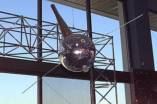
Vanguard 1 is an American satellite that was the fourth artificial Earth-orbiting satellite to be successfully launched, following Sputnik 1, Sputnik 2, and Explorer 1. It was launched 17 March 1958. Vanguard 1 was the first satellite to have solar electric power. Although communications with the satellite were lost in 1964, it remains the oldest human-made object still in orbit, together with the upper stage of its launch vehicle.

<span class="mw-page-title-main">Vanguard 3</span>

Vanguard 3 is a scientific satellite that was launched into Earth orbit by the Vanguard SLV-7 on 18 September 1959, the third successful Vanguard launch out of eleven attempts. Vanguard rocket: Vanguard Satellite Launch Vehicle-7 (SLV-7) was an unused Vanguard TV-4BU rocket, updated to the final production Satellite Launch Vehicle (SLV).

<span class="mw-page-title-main">Project Echo</span> First passive communications satellite experiment

Project Echo was the first passive communications satellite experiment. Each of the two American spacecraft, launched in 1960 and 1964, were metalized balloon satellites acting as passive reflectors of microwave signals. Communication signals were transmitted from one location on Earth and bounced off the surface of the satellite to another Earth location.

<span class="mw-page-title-main">Explorer 6</span> NASA satellite of the Explorer program

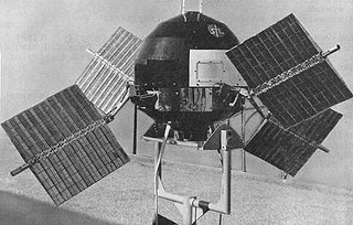
Explorer 6, or S-2, was a NASA satellite, launched on 7 August 1959, at 14:24:20 GMT. It was a small, spheroidal satellite designed to study trapped radiation of various energies, galactic cosmic rays, geomagnetism, radio propagation in the upper atmosphere, and the flux of micrometeorites. It also tested a scanning device designed for photographing the Earth's cloud cover. On 14 August 1959, Explorer 6 took the first photos of Earth from a satellite.

<span class="mw-page-title-main">Explorer 52</span> NASA satellite of the Explorer program

Explorer 52, also known as Hawkeye-1, Injun-F, Neutral Point Explorer, IE-D, Ionospheric Explorer-D, was a NASA satellite launched on 3 June 1974, from Vandenberg Air Force Base on a Scout E-1 launch vehicle.

<span class="mw-page-title-main">Explorer 33</span> NASA satellite of the Explorer program (1966–)

Explorer 33, also known as IMP-D and AIMP-1, is a spacecraft in the Explorer program launched by NASA on 1 July 1966 on a mission of scientific exploration. It was the fourth satellite launched as part of the Interplanetary Monitoring Platform series, and the first of two "Anchored IMP" spacecraft to study the environment around Earth at lunar distances, aiding the Apollo program. It marked a departure in design from its predecessors, IMP-A through IMP-C. Explorer 35 was the companion spacecraft to Explorer 33 in the Anchored IMP program, but Explorer 34 (IMP-F) was the next spacecraft to fly, launching about two months before AIMP-E, both in 1967.

<span class="mw-page-title-main">Explorer 61</span> NASA satellite of the Explorer program

Magsat was a NASA/USGS spacecraft, launched on 30 October 1979. The mission was to map the Earth's magnetic field, the satellite had two magnetometers. The scalar and vector magnetometers gave Magsat a capability beyond that of any previous spacecraft. Extended by a telescoping boom, the magnetometers were distanced from the magnetic field created by the satellite and its electronics. The satellite carried two magnetometers, a three-axis fluxgate magnetometer for determining the strength and direction of magnetic fields, and an ion-vapor/vector magnetometer for determining the magnetic field caused by the vector magnetometer itself. Magsat is considered to be one of the more important Science/Earth orbiting satellites launched; the data it accumulated is still being used, particularly in linking new satellite data to past observations.

<span class="mw-page-title-main">Explorer 18</span> NASA satellite of the Explorer program

Explorer 18, also called IMP-A, IMP-1, Interplanetary Monitoring Platform-1 and S-74, was a NASA satellite launched as part of the Explorer program. Explorer 18 was launched on 27 November 1963 from Cape Canaveral Air Force Station (CCAFS), Florida, with a Thor-Delta C launch vehicle. Explorer 18 was the first satellite of the Interplanetary Monitoring Platform (IMP). Explorer 21 (IMP-B) launched in October 1964 and Explorer 28 (IMP-C) launched in May 1965 also used the same general spacecraft design.

<span class="mw-page-title-main">Explorer 10</span> NASA satellite of the Explorer program

Explorer 10 was a NASA satellite that investigated Earth's magnetic field and nearby plasma. Launched on 25 March 1961, it was an early mission in the Explorer program and was the first satellite to measure the "shock wave" generated by a solar flare.

<span class="mw-page-title-main">GEOS-3</span> Satellite

GEOS-3, or Geodynamics Experimental Ocean Satellite 3, or GEOS-C, was the third and final satellite as part of NASA's Geodetic Earth Orbiting Satellite/Geodynamics Experimental Ocean Satellite program (NGSP) to better understand and test satellite tracking systems. For GEOS 1 and GEOS 2, the acronym stands for Geodetic Earth Orbiting Satellite; this was changed for GEOS-3.

<span class="mw-page-title-main">ISEE-2</span>

The ISEE-2 was an Explorer-class daughter spacecraft, International Sun-Earth Explorer-2, was part of the mother/daughter/heliocentric mission. ISEE-2 was a 165.78 kg (365.5 lb) space probe used to study magnetic fields near the Earth. ISEE-2 was a spin-stabilized spacecraft and based on the design of the prior IMP series of spacecraft. ISEE-1 and ISEE-2 were launched on 22 October 1977, and they re-entered on 26 September 1987.

<span class="mw-page-title-main">Explorer 12</span> NASA satellite of the Explorer program

Explorer 12, also called EPE-A or Energetic Particles Explorer-A and as S3), was a NASA satellite built to measure the solar wind, cosmic rays, and the Earth's magnetic field. It was the first of the S-3 series of spacecraft, which also included Explorer 12, 14, 15, and 26. It was launched on 16 August 1961, aboard a Thor-Delta launch vehicle. It ceased transmitting on 6 December 1961 due to power failure.

<span class="mw-page-title-main">Explorer 27</span> NASA satellite of the Explorer program

Explorer 27 was a small NASA satellite, launched in 1965, designed to conduct scientific research in the ionosphere. It was powered by 4 solar panels. One goal of the mission was to study in detail the shape of the Earth by way of investigating variations in its gravitational field. It was the third and last of the Beacons in the Explorers program. The satellite was shut off in July 1973 so that its transmission band could be used by higher-priority spacecraft.

<span class="mw-page-title-main">Explorer 28</span> NASA satellite of the Explorer program

Explorer 28, also called IMP-C, IMP-3 and Interplanetary Monitoring Platform-3, was a NASA satellite launched on 29 May 1965 to study space physics, and was the third spacecraft launched in the Interplanetary Monitoring Platform program. It was powered by chemical batteries and solar panels. There were 7 experiments on board, all devoted to particle studies. Performance was normal until late April 1967, when intermittent problems began. It stayed in contact until 12 May 1967, when contact was lost. The orbit decayed until it re-entered the atmosphere on 4 July 1968. The spacecraft design was similar to its predecessors Explorer 18 (IMP-A), launched in November 1963, and Explorer 21 (IMP-B), launched in October 1964, though this satellite was a few kilograms lighter. The successor Explorer 33 (IMP-D) began the use of a new design.

<span class="mw-page-title-main">Explorer S-66</span> NASA satellite of the Explorer program

Explorer S-66, was a NASA satellite launched on 19 March 1964 by means of a Thor-Delta B launch vehicle, but it could not reach orbit due to a vehicle launcher failure.

<span class="mw-page-title-main">Explorer 22</span> NASA satellite of the Explorer program

Explorer 22 was a small NASA ionospheric research satellite launched 9 October 1964, part of NASA's Explorer Program. It was instrumented with an electrostatic probe, four radio beacons for ionospheric research, a passive laser tracking reflector, and two radio beacons for Doppler navigation experiments. Its objective was to provide enhanced geodetic measurements of the Earth as well as data on the total electron content in the Earth's atmosphere and in the satellite's immediate vicinity.

<span class="mw-page-title-main">Explorer 29</span> NASA satellite of the Explorer program

Explorer 29, also called GEOS 1 or GEOS A, acronym to Geodetic Earth Orbiting Satellite, was a NASA satellite launched as part of the Explorer program, being the first of the two satellites GEOS. Explorer 29 was launched on 6 November 1965 from Cape Canaveral, Florida, with a Thor-Delta E launch vehicle.

NOAA-14, also known as NOAA-J before launch, was an American weather satellite operated by the National Oceanic and Atmospheric Administration (NOAA). NOAA-14 continued the third-generation operational, Polar Orbiting Environmental Satellite (POES) series operated by the National Environmental Satellite Service (NESS) of the National Oceanic and Atmospheric Administration (NOAA). NOAA-14 continued the series of Advanced TIROS-N (ATN) spacecraft begun with the launch of NOAA-8 (NOAA-E) in 1983.

AMPTE-IRM, also called as AMPTE-Ion Release Module, was a Germany satellite designed and tasked to study the magnetosphere of Earth, being launched as part of the Explorer program. The AMPTE mission was designed to study the access of solar wind ions to the magnetosphere, the convective-diffusive transport and energization of magnetospheric particles, and the interactions of plasmas in space.

AMPTE-UKS, also called as AMPTE-United Kingdom Subsatellite, was a United Kingdom satellite designed and tasked to study the magnetosphere of Earth, being launched as part of the Explorer program. The AMPTE mission was designed to study the access of solar wind ions to the magnetosphere, the convective-diffusive transport and energization of magnetospheric particles, and the interactions of plasmas in space.

References

  1. "GEOS". Encyclopedia Astronautica. Mark Wade. Archived from the original on 27 September 2016. Retrieved 17 June 2018.
  2. McDowell, Jonathan (21 July 2021). "Launch Log". Jonathan's Space Report. Retrieved 11 November 2021.
  3. Antonín Vítek, Lubor Lejček (17 January 2012). "1968-002A - Explorer 36" (in Czech). Space 40. Retrieved 17 June 2018.
  4. "Trajectory: Explorer 36 (GEOS 2) 1968-002A". NASA. 28 October 2021. Retrieved 12 November 2021.PD-icon.svg This article incorporates text from this source, which is in the public domain.
  5. "The GEOS-II Heat Pipe System and Its Performance in Test and Orbit" (PDF). Johns Hopkins. April 1969. Retrieved 2 May 2024.PD-icon.svg This article incorporates text from this source, which is in the public domain .
  6. "Explorer 26 (GEOS 2) 1968-002A". NASA. 28 October 2021. Retrieved 12 November 2021.PD-icon.svg This article incorporates text from this source, which is in the public domain .
  7. "Experiment: C-Band Radar Transponder". NASA. 28 October 2021. Retrieved 12 November 2021.PD-icon.svg This article incorporates text from this source, which is in the public domain .
  8. "Experiment: Laser Tracking Reflector". NASA. 28 October 2021. Retrieved 12 November 2021.PD-icon.svg This article incorporates text from this source, which is in the public domain .
  9. "Experiment: Magnetometer". NASA. 28 October 2021. Retrieved 12 November 2021.PD-icon.svg This article incorporates text from this source, which is in the public domain .
  10. "Experiment: NASA Minitrack System". NASA. 28 October 2021. Retrieved 12 November 2021.PD-icon.svg This article incorporates text from this source, which is in the public domain .
  11. "Experiment: Optical Beacon System". NASA. 28 October 2021. Retrieved 12 November 2021.PD-icon.svg This article incorporates text from this source, which is in the public domain .
  12. "Experiment: Precipitating Electron Detector". NASA. 28 October 2021. Retrieved 12 November 2021.PD-icon.svg This article incorporates text from this source, which is in the public domain .
  13. "Experiment: Radio Doppler System". NASA. 28 October 2021. Retrieved 12 November 2021.PD-icon.svg This article incorporates text from this source, which is in the public domain .
  14. "Experiment: Radio Range/Rate System". NASA. 28 October 2021. Retrieved 12 November 2021.PD-icon.svg This article incorporates text from this source, which is in the public domain .
  15. "Experiment: SECOR Range Transponder". NASA. 28 October 2021. Retrieved 12 November 2021.PD-icon.svg This article incorporates text from this source, which is in the public domain .