Full color image along with its R, G, and B componentsAdditive color mixing demonstrated with CD covers used as beam splittersA diagram demonstrating additive color with RGB
The main purpose of the RGB color model is for the sensing, representation, and display of images in electronic systems, such as televisions and computers, though it has also been used in conventional photography and colored lighting. Before the electronic age, the RGB color model already had a solid theory behind it, based in human perception of colors.
RGB is a device-dependent color model: different devices detect or reproduce a given RGB value differently, since the color elements (such as phosphors or dyes) and their response to the individual red, green, and blue levels vary from manufacturer to manufacturer, or even in the same device over time. Thus an RGB value does not define the same color across devices without some kind of color management.[3][4]
Additive color mixing: projecting primary color lights on a white surface shows secondary colors where two overlap; the combination of all three primaries in equal intensities makes white.
To form a color with RGB, three light beams (one red, one green, and one blue) must be superimposed (for example by emission from a black screen or by reflection from a white screen). Each of the three beams is called a component of that color, and each of them can have an arbitrary intensity, from fully off to fully on, in the mixture.
The RGB color model is additive in the sense that if light beams of differing color (frequency) are superposed in space their light spectra adds up, wavelength for wavelength, to make up a resulting, total spectrum.[5][6] This is in contrast to the subtractive color model, particularly the CMY Color Model, which applies to paints, inks, dyes and other substances whose color depends on reflecting certain components (frequencies) of the light under which they are seen.
In the additive model, if the resulting spectrum, e.g. of superposing three colors, is flat, white color is perceived by the human eye upon direct incidence on the retina. This is in stark contrast to the subtractive model, where the perceived resulting spectrum is what reflecting surfaces, such as dyed surfaces, emit. A dye filters out all colors but its own; two blended dyes filter out all colors but the common color component between them, e.g. green as the common component between yellow and cyan, red as the common component between magenta and yellow, and blue-violet as the common component between magenta and cyan. There is no common color component among magenta, cyan and yellow, thus rendering a spectrum of zero intensity: black.
Zero intensity for each component gives the darkest color (no light, considered the black), and full intensity of each gives a white; the quality of this white depends on the nature of the primary light sources, but if they are properly balanced, the result is a neutral white matching the system's white point. When the intensities for all the components are the same, the result is a shade of gray, darker, or lighter depending on the intensity. When the intensities are different, the result is a colorized hue, more or less saturated depending on the difference of the strongest and weakest of the intensities of the primary colors employed.
When one of the components has the strongest intensity, the color is a hue near this primary color (red-ish, green-ish, or blue-ish), and when two components have the same strongest intensity, then the color is a hue of a secondary color (a shade of cyan, magenta, or yellow). A secondary color is formed by the sum of two primary colors of equal intensity: cyan is green+blue, magenta is blue+red, and yellow is red+green. Every secondary color is the complement of one primary color: cyan complements red, magenta complements green, and yellow complements blue. When all the primary colors are mixed in equal intensities, the result is white.
The RGB color model itself does not define what is meant by red, green, and blue colorimetrically, and so the results of mixing them are not specified as absolute, but relative to the primary colors. When the exact chromaticities of the red, green, and blue primaries are defined, the color model then becomes an absolute color space, such as sRGB or Adobe RGB.
Physical principles for the choice of red, green, and blue
A set of primary colors, such as the sRGB primaries, define a color triangle; only colors within this triangle can be reproduced by mixing the primary colors. Colors outside the color triangle are therefore shown here as gray. The primaries and the D65white point of sRGB are shown. The background figure is the CIE xy chromaticity diagram.
The choice of primary colors is related to the physiology of the human eye; good primaries are stimuli that maximize the difference between the responses of the cone cells of the human retina to light of different wavelengths, and that thereby make a large color triangle.[7]
The normal three kinds of light-sensitive photoreceptor cells in the human eye (cone cells) respond most to yellow (long wavelength or L), green (medium or M), and violet (short or S) light (peak wavelengths near 570nm, 540nm and 440nm, respectively[7]). The difference in the signals received from the three kinds allows the brain to differentiate a wide gamut of different colors, while being most sensitive (overall) to yellowish-green light and to differences between hues in the green-to-orange region.
As an example, suppose that light in the orange range of wavelengths (approximately 577nm to 597nm) enters the eye and strikes the retina. Light of these wavelengths would activate both the medium and long wavelength cones of the retina, but not equally—the long-wavelength cells will respond more. The difference in the response can be detected by the brain, and this difference is the basis of our perception of orange. Thus, the orange appearance of an object results from light from the object entering our eye and stimulating the different cones simultaneously but to different degrees.
Use of the three primary colors is not sufficient to reproduce all colors; only colors within the color triangle defined by the chromaticities of the primaries can be reproduced by additive mixing of non-negative amounts of those colors of light.[7][pageneeded]
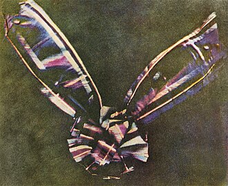
The first permanent color photograph, taken by Thomas Sutton in 1861 using James Clerk Maxwell's proposed method of three filters, specifically red, green, and violet-blue
The first experiments with RGB in early color photography were made in 1861 by Maxwell himself, and involved the process of combining three color-filtered separate takes.[1] To reproduce the color photograph, three matching projections over a screen in a dark room were necessary.
The additive RGB model and variants such as orange–green–violet were also used in the Autochrome Lumière color plates and other screen-plate technologies such as the Joly color screen and the Paget process in the early twentieth century. Color photography by taking three separate plates was used by other pioneers, such as the Russian Sergey Prokudin-Gorsky in the period 1909 through 1915.[8] Such methods lasted until about 1960 using the expensive and extremely complex tri-color carbroAutotype process.[9]
When employed, the reproduction of prints from three-plate photos was done by dyes or pigments using the complementary CMY model, by simply using the negative plates of the filtered takes: reverse red gives the cyan plate, and so on.
Television
Before the development of practical electronic TV, there were patents on mechanically scanned color systems as early as 1889 in Russia. The color TV pioneer John Logie Baird demonstrated the world's first RGB color transmission in 1928, and also the world's first color broadcast in 1938, in London. In his experiments, scanning and display were done mechanically by spinning colorized wheels.[10][11]
The Columbia Broadcasting System (CBS) began an experimental RGB field-sequential color system in 1940. Images were scanned electrically, but the system still used a moving part: the transparent RGB color wheel rotating at above 1,200rpm in synchronism with the vertical scan. The camera and the cathode-ray tube (CRT) were both monochromatic. Color was provided by color wheels in the camera and the receiver.[12][13][14] More recently, color wheels have been used in field-sequential projection TV receivers based on the Texas Instruments monochrome DLP imager.
The modern RGB shadow mask technology for color CRT displays was patented by Werner Flechsig in Germany in 1938.[15]
Personal computers
Personal computers of the late 1970s and early 1980s, such as the Apple II and VIC-20, use composite video. The Commodore 64 and the Atari 8-bit computers use S-Video derivatives. IBM introduced a 16-color scheme (4bits—1bit each for red, green, blue, and intensity) with the Color Graphics Adapter (CGA) for its IBM PC in 1981, later improved with the Enhanced Graphics Adapter (EGA) in 1984. The first manufacturer of a truecolor graphics card for PCs (the TARGA) was Truevision in 1987, but it was not until the arrival of the Video Graphics Array (VGA) in 1987 that RGB became popular, mainly due to the analog signals in the connection between the adapter and the monitor which allowed a very wide range of RGB colors. Actually, it had to wait a few more years because the original VGA cards were palette-driven just like EGA, although with more freedom than VGA, but because the VGA connectors were analog, later variants of VGA (made by various manufacturers under the informal name Super VGA) eventually added true-color. In 1992, magazines heavily advertised true-color Super VGA hardware.
RGB devices
RGB and displays
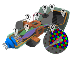
Cutaway rendering of a color CRT: 1.Electron guns 2.Electron beams 3.Focusing coils 4.Deflection coils 5.Anode connection 6.Mask for separating beams for red, green, and blue part of displayed image 7.Phosphor layer with red, green, and blue zones 8.Close-up of the phosphor-coated inner side of the screenColor wheel with RGB pixels of the colorsRGB phosphor dots in a CRT monitorRGB sub-pixels in an LCD TV (on the right: an orange and a blue color; on the left: a close-up)
One common application of the RGB color model is the display of colors on a cathode-ray tube (CRT), liquid-crystal display (LCD), plasma display, or organic light emitting diode (OLED) display such as a television, a computer's monitor, or a large scale screen. Each pixel on the screen is built by driving three small and very close but still separated RGB light sources. At common viewing distance, the separate sources are indistinguishable, which the eye interprets as a given solid color. All the pixels together arranged in the rectangular screen surface conforms the color image.
During digital image processing each pixel can be represented in the computer memory or interface hardware (for example, a graphics card) as binary values for the red, green, and blue color components. When properly managed, these values are converted into intensities or voltages via gamma correction to correct the inherent nonlinearity of some devices, such that the intended intensities are reproduced on the display.
The Quattron released by Sharp uses RGB color and adds yellow as a sub-pixel, supposedly allowing an increase in the number of available colors.
RGB is also the term referring to a type of component video signal used in the video electronics industry. It consists of three signals—red, green, and blue—carried on three separate cables/pins. RGB signal formats are often based on modified versions of the RS-170 and RS-343 standards for monochrome video. This type of video signal is widely used in Europe since it is the best quality signal that can be carried on the standard SCART connector.[16][17] This signal is known as RGBS (4 BNC/RCA terminated cables exist as well), but it is directly compatible with RGBHV used for computer monitors (usually carried on 15-pin cables terminated with 15-pin D-sub or 5 BNC connectors), which carries separate horizontal and vertical sync signals.
Outside Europe, RGB is not very popular as a video signal format; S-Video takes that spot in most non-European regions. However, almost all computer monitors around the world use RGB.
Video framebuffer
A framebuffer is a digital device for computers which stores data in the so-called video memory (comprising an array of Video RAM or similar chips). This data goes either to three digital-to-analog converters (DACs) (for analog monitors), one per primary color or directly to digital monitors. Driven by software, the CPU (or other specialized chips) write the appropriate bytes into the video memory to define the image. Modern systems encode pixel color values by devoting 8bits to each of the R, G, and B components. RGB information can be either carried directly by the pixel bits themselves or provided by a separate color look-up table (CLUT) if indexed color graphic modes are used.
A CLUT is a specialized RAM that stores R, G, and B values that define specific colors. Each color has its own address (index)—consider it as a descriptive reference number that provides that specific color when the image needs it. The content of the CLUT is much like a palette of colors. Image data that uses indexed color specifies addresses within the CLUT to provide the required R, G, and B values for each specific pixel, one pixel at a time. Of course, before displaying, the CLUT has to be loaded with R, G, and B values that define the palette of colors required for each image to be rendered. Some video applications store such palettes in PAL files (Age of Empires game, for example, uses over half-a-dozen[18]) and can combine CLUTs on screen.
RGB24 and RGB32
This indirect scheme restricts the number of available colors in an image CLUT—typically 256-cubed (8bits in three color channels with values of 0–255)—although each color in the RGB24 CLUT table has only 8bits representing 256 codes for each of the R, G, and B primaries, making 16,777,216 possible colors. However, the advantage is that an indexed-color image file can be significantly smaller than it would be with only 8bits per pixel for each primary.
Modern storage, however, is far less costly, greatly reducing the need to minimize image file size. By using an appropriate combination of red, green, and blue intensities, many colors can be displayed. Current typical display adapters use up to 24bits of information for each pixel: 8-bit per component multiplied by three components (see the Numeric representations section below (24bits=2563, each primary value of 8bits with values of 0–255). With this system, 16,777,216 (2563 or 224) discrete combinations of R, G, and B values are allowed, providing millions of different (though not necessarily distinguishable) hue, saturation and lightness shades. Increased shading has been implemented in various ways, some formats such as .png and .tga files among others using a fourth grayscale color channel as a masking layer, often called RGB32.
For images with a modest range of brightnesses from the darkest to the lightest, 8bits per primary color provides good-quality images, but extreme images require more bits per primary color as well as the advanced display technology. For more information see High Dynamic Range (HDR) imaging.
In classic CRT devices, the brightness of a given point over the fluorescent screen due to the impact of accelerated electrons is not proportional to the voltages applied to the electron gun control grids, but to an expansive function of that voltage. The amount of this deviation is known as its gamma value (), the argument for a power law function, which closely describes this behavior. A linear response is given by a gamma value of 1.0, but actual CRT nonlinearities have a gamma value around 2.0 to 2.5.
Similarly, the intensity of the output on TV and computer display devices is not directly proportional to the R, G, and B applied electric signals (or file data values which drive them through digital-to-analog converters). On a typical standard 2.2-gamma CRT display, an input intensity RGB value of (0.5,0.5,0.5) only outputs about 22% of full brightness (1.0,1.0,1.0), instead of 50%.[19] To obtain the correct response, a gamma correction is used in encoding the image data, and possibly further corrections as part of the color calibration process of the device. Gamma affects black-and-white TV as well as color. In standard color TV, broadcast signals are gamma corrected.
RGB and cameras
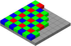
The Bayer filter arrangement of color filters on the pixel array of a digital image sensor
In color television and video cameras manufactured before the 1990s, the incoming light was separated by prisms and filters into the three RGB primary colors feeding each color into a separate video camera tube (or pickup tube). These tubes are a type of cathode-ray tube, not to be confused with that of CRT displays.
With the arrival of commercially viable charge-coupled device (CCD) technology in the 1980s, first, the pickup tubes were replaced with this kind of sensor. Later, higher scale integration electronics was applied (mainly by Sony), simplifying and even removing the intermediate optics, thereby reducing the size of home video cameras and eventually leading to the development of full camcorders. Current webcams and mobile phones with cameras are the most miniaturized commercial forms of such technology.
Photographic digital cameras that use a CMOS or CCD image sensor often operate with some variation of the RGB model. In a Bayer filter arrangement, green is given twice as many detectors as red and blue (ratio 1:2:1) in order to achieve higher luminance resolution than chrominance resolution. The sensor has a grid of red, green, and blue detectors arranged so that the first row is RGRGRGRG, the next is GBGBGBGB, and that sequence is repeated in subsequent rows. For every channel, missing pixels are obtained by interpolation in the demosaicing process to build up the complete image. Also, other processes used to be applied in order to map the camera RGB measurements into a standard color space as sRGB.
RGB and scanners
In computing, an image scanner is a device that optically scans images (printed text, handwriting, or an object) and converts it to a digital image which is transferred to a computer. Among other formats, flat, drum and film scanners exist, and most of them support RGB color. They can be considered the successors of early telephotography input devices, which were able to send consecutive scan lines as analogamplitude modulation signals through standard telephonic lines to appropriate receivers; such systems were in use in press since the 1920s to the mid-1990s. Color telephotographs were sent as three separated RGB filtered images consecutively.
Currently available scanners typically use CCD or contact image sensor (CIS) as the image sensor, whereas older drum scanners use a photomultiplier tube as the image sensor. Early color film scanners used a halogen lamp and a three-color filter wheel, so three exposures were needed to scan a single color image. Due to heating problems, the worst of them being the potential destruction of the scanned film, this technology was later replaced by non-heating light sources such as color LEDs.
Numeric representations
#FFCCCC
#FFC0C0
#FF9999
#FF8080
#FF6666
#FF4040
#FF3333
#FF0000
#FFE5CC
#FFE0C0
#FFCC99
#FFC080
#FFB266
#FFA040
#FF9933
#FF8000
#FFFFCC
#FFFFC0
#FFFF99
#FFFF80
#FFFF66
#FFFF40
#FFFF33
#FFFF00
#FFFFE5
#FFFFE0
#FFFFCC
#FFFFC0
#FFFFB2
#FFFFA0
#FFFF99
#FFFF80
#E5FFCC
#E0FFC0
#CCFF99
#C0FFA0
#B2FF66
#A0FF40
#99FF33
#80FF00
#CCFFCC
#C0FFC0
#99FF99
#80FF80
#66FF66
#40FF40
#33FF33
#00FF00
#E5FFE5
#E0FFE0
#CCFFCC
#C0FFC0
#B2FFB2
#A0FFA0
#99FF99
#80FF80
#CCE5CC
#C0E0C0
#99CC99
#80C080
#66B266
#40A040
#339933
#008000
#CCFFE5
#C0FFE0
#99FFCC
#80FFC0
#66FFB2
#40FFA0
#33FF99
#00FF80
#CCFFFF
#C0FFFF
#99FFFF
#80FFFF
#66FFFF
#40FFFF
#33FFFF
#00FFFF
#E5FFFF
#E0FFFF
#CCFFFF
#C0FFFF
#B2FFFF
#A0FFFF
#99FFFF
#80FFFF
#CCE5E5
#C0E0E0
#99CCCC
#80C0C0
#66B2B2
#40A0A0
#339999
#008080
#CCE5FF
#C0E0FF
#99CCFF
#80C0FF
#66B2FF
#40A0FF
#3399FF
#0080FF
#CCCCFF
#C0C0FF
#9999FF
#8080FF
#6666FF
#4040FF
#3333FF
#0000FF
#CCCCE5
#C0C0E0
#9999CC
#8080C0
#6666B2
#4040A0
#333399
#000080
#E5E5FF
#E0E0FF
#CCCCFF
#C0C0FF
#B2B2FF
#A0A0FF
#9999FF
#8080FF
#E5CCFF
#E0C0FF
#CC99FF
#C080FF
#B266FF
#A040FF
#9933FF
#8000FF
#E5CCE5
#E0C0E0
#CC99CC
#C080C0
#B266B2
#A040A0
#993399
#800080
#FFCCFF
#FFC0FF
#FF99FF
#FF80FF
#FF66FF
#FF40FF
#FF33FF
#FF00FF
#FFE5FF
#FFE0FF
#FFCCFF
#FFC0FF
#FFB2FF
#FFA0FF
#FF99FF
#FF80FF
#FFCCE5
#FFC0E0
#FF99CC
#FF80C0
#FF66B2
#FF40A0
#FF3399
#FF0080
#FFE5E5
#FFE0E0
#FFCCCC
#FFC0C0
#FFB2B2
#FFA0A0
#FF9999
#FF8080
#E5CCCC
#E0C0C0
#CC9999
#C08080
#B26666
#A04040
#993333
#800000
#E5E5CC
#E0E0C0
#CCCC99
#C0C080
#B2B266
#A0A040
#999933
#808000
#E5E5E5
#E0E0E0
#CCCCCC
#C0C0C0
#B2B2B2
#A0A0A0
#999999
#808080
#FF0000
#CC0000
#C00000
#990000
#800000
#660000
#400000
#330000
#FF8000
#CC6600
#C06000
#994C00
#804000
#663300
#402000
#331900
#FFFF00
#CCCC00
#C0C000
#999900
#808000
#666600
#404000
#333300
#FFFF80
#CCCC66
#C0C060
#99994C
#808040
#666633
#404020
#333319
#80FF00
#66CC00
#60C000
#4C9900
#408000
#336600
#204000
#193300
#00FF00
#00CC00
#00C000
#009900
#008000
#006600
#004000
#003300
#80FF80
#66CC66
#60C060
#4C994C
#408040
#336633
#204020
#193319
#008000
#006600
#006000
#004C00
#004000
#003300
#002000
#001900
#00FF80
#00CC66
#00C060
#00994C
#008040
#006633
#004020
#003319
#00FFFF
#00CCCC
#00C0C0
#009999
#008080
#006666
#004040
#003333
#80FFFF
#66CCCC
#60C0C0
#4C9999
#408080
#336666
#204040
#193333
#008080
#006666
#006060
#004C4C
#004040
#003333
#002020
#001919
#0080FF
#0066CC
#0060C0
#004C99
#004080
#003366
#002040
#001933
#0000FF
#0000CC
#0000C0
#000099
#000080
#000066
#000040
#000033
#000080
#000066
#000060
#00004C
#000040
#000033
#000020
#000019
#8080FF
#6666CC
#6060C0
#4C4C99
#404080
#333366
#202040
#191933
#8000FF
#6600CC
#6000C0
#4C0099
#400080
#330066
#200040
#190033
#800080
#660066
#600060
#4C004C
#400040
#330033
#200020
#190019
#FF00FF
#CC00CC
#C000C0
#990099
#800080
#660066
#400040
#330033
#FF80FF
#CC66CC
#C060C0
#994C99
#804080
#663366
#402040
#331933
#FF0080
#CC0066
#C00060
#99004C
#800040
#660033
#400020
#330019
#FF8080
#CC6666
#C06060
#994C4C
#804040
#663333
#402020
#331919
#800000
#660000
#600000
#4C0000
#400000
#330000
#200000
#190000
#808000
#666600
#606000
#4C4C00
#404000
#333300
#202000
#191900
#808080
#666666
#606060
#4C4C4C
#404040
#333333
#202020
#191919
R:128
128
G:200
200
B:255
255
#80C8FF
A typical RGB color selector. Each slider ranges from 0 to 255.
Hexadecimal 8-bit RGB representations of the main 125 colors
A color in the RGB color model is described by indicating how much of each of the red, green, and blue is included. The color is expressed as an RGB triplet (r,g,b), each component of which can vary from zero to a defined maximum value. If all the components are at zero the result is black; if all are at maximum, the result is the brightest representable white.
These ranges may be quantified in several different ways:
From 0 to 1, with any fractional value in between. This representation is used in theoretical analyses, and in systems that use floating point representations.
Each color component value can also be written as a percentage, from 0% to 100%.
In computers, the component values are often stored as unsigned integer numbers in the range 0 to 255, the range that a single 8-bit byte can offer. These are often represented as either decimal or hexadecimal numbers.
High-end digital image equipment are often able to deal with larger integer ranges for each primary color, such as 0..1023 (10bits), 0..65535 (16bits) or even larger, by extending the 24bits (three 8-bit values) to 32-bit, 48-bit, or 64-bit units (more or less independent from the particular computer's word size).
For example, brightest saturated red is written in the different RGB notations as:
Notation
RGB triplet
Arithmetic
(1.0, 0.0, 0.0)
Percentage
(100%, 0%, 0%)
Digital 8-bit per channel
(255, 0, 0) #FF0000 (hexadecimal)
Digital 12-bit per channel
(4095, 0, 0) #FFF000000
Digital 16-bit per channel
(65535, 0, 0) #FFFF00000000
Digital 24-bit per channel
(16777215, 0, 0) #FFFFFF000000000000
Digital 32-bit per channel
(4294967295, 0, 0) #FFFFFFFF0000000000000000
In many environments, the component values within the ranges are not managed as linear (that is, the numbers are nonlinearly related to the intensities that they represent), as in digital cameras and TV broadcasting and receiving due to gamma correction, for example.[20] Linear and nonlinear transformations are often dealt with via digital image processing. Representations with only 8bits per component are considered sufficient if gamma correction is used.[21]
Following is the mathematical relationship between RGB space to HSI space (hue, saturation, and intensity: HSI color space):
The RGB color model is one of the most common ways to encode color in computing, and several different digital representations are in use. The main characteristic of all of them is the quantization of the possible values per component (technically a sample) by using only integer numbers within some range, usually from 0 to some power of two minus one (2n−1) to fit them into some bit groupings. Encodings of 1, 2, 4, 5, 8, and 16bits per color are commonly found; the total number of bits used for an RGB color is typically called the color depth.
The RGB color model mapped to a cube. The horizontal x-axis as red values increasing to the left, y-axis as blue increasing to the lower right and the vertical z-axis as green increasing towards the top. The origin, black is the vertex hidden from view.
Since colors are usually defined by three components, not only in the RGB model, but also in other color models such as CIELAB and Y'UV, among others, then a three-dimensionalvolume is described by treating the component values as ordinary Cartesian coordinates in a Euclidean space. For the RGB model, this is represented by a cube using non-negative values within a 0–1 range, assigning black to the origin at the vertex (0,0,0), and with increasing intensity values running along the three axes up to white at the vertex (1,1,1), diagonally opposite black.
An RGB triplet (r,g,b) represents the three-dimensional coordinate of the point of the given color within the cube or its faces or along its edges. This approach allows computations of the color similarity of two given RGB colors by simply calculating the distance between them: the shorter the distance, the higher the similarity. Out-of-gamut computations can also be performed this way.
Initially, the limited color depth of most video hardware led to a limited color palette of 216 RGB colors, defined by the Netscape Color Cube. The web-safe color palette consists of the 216 (63) combinations of red, green, and blue where each color can take one of six values (in hexadecimal): #00, #33, #66, #99, #CC or #FF (based on the 0 to 255 range for each value discussed above). These hexadecimal values= 0, 51, 102, 153, 204, 255 in decimal, which= 0%, 20%, 40%, 60%, 80%, 100% in terms of intensity. This seems fine for splitting up 216 colors into a cube of dimension 6. However, lacking gamma correction, the perceived intensity on a standard 2.5 gamma CRT / LCD is only: 0%, 2%, 10%, 28%, 57%, 100%. See the actual web safe color palette for a visual confirmation that the majority of the colors produced are very dark.[22]
With the predominance of 24-bit displays, the use of the full 16.7million colors of the HTML RGB color code no longer poses problems for most viewers. The sRGB color space (a device-independent color space[23]) for HTML was formally adopted as an Internet standard in HTML 3.2,[24][25] though it had been in use for some time before that. All images and colors are interpreted as being sRGB (unless another color space is specified) and all modern displays can display this color space (with color management being built in into browsers[26][27] or operating systems[28]).
where # equals the proportion of red, green, and blue respectively. This syntax can be used after such selectors as "background-color:" or (for text) "color:".
Wide gamut color is possible in modern CSS,[29] being supported by all major browsers since 2023.[30][31][32]
For example, a color on the DCI-P3 color space can be indicated as:
color(display-p3 # # #)
where # equals the proportion of red, green, and blue in 0.0 to 1.0 respectively.
Proper reproduction of colors, especially in professional environments, requires color management of all the devices involved in the production process, many of them using RGB. Color management results in several transparent conversions between device-independent (sRGB, XYZ, L*a*b*)[23] and device-dependent color spaces (RGB and others, as CMYK for color printing) during a typical production cycle, in order to ensure color consistency throughout the process. Along with the creative processing, such interventions on digital images can damage the color accuracy and image detail, especially where the gamut is reduced. Professional digital devices and software tools allow for 48bpp (bits per pixel) images to be manipulated (16bits per channel), to minimize any such damage.
RGB model and luminance–chrominance formats relationship
All luminance–chrominance formats used in the different TV and video standards such as YIQ for NTSC, YUV for PAL, YDBDR for SECAM, and YPBPR for component video use color difference signals, by which RGB color images can be encoded for broadcasting/recording and later decoded into RGB again to display them. These intermediate formats were needed for compatibility with pre-existent black-and-white TV formats. Also, those color difference signals need lower data bandwidth compared to full RGB signals.
Similarly, current high-efficiency digital color image data compression schemes such as JPEG and MPEG store RGB color internally in YCBCR format, a digital luminance–chrominance format based on YPBPR. The use of YCBCR also allows computers to perform lossysubsampling with the chrominance channels (typically to 4:2:2 or 4:1:1 ratios), which reduces the resultant file size.
↑Fairman, Hugh S.; Brill, Michael H.; Hemmendinger, Henry (February 1997). "How the CIE 1931 color-matching functions were derived from Wright-Guild data". Color Research & Application. 22 (1): 11–23. doi:10.1002/(SICI)1520-6378(199702)22:1<11::AID-COL4>3.0.CO;2-7. The first of the resolutions offered to the 1931 meeting defined the color-matching functions of the soon-to-be-adopted standard observer in terms of Guild's spectral primaries centered on wavelengths 435.8, 546.1, and 700nm. Guild approached the problem from the viewpoint of a standardization engineer. In his mind, the adopted primaries had to be producible with national-standardizing-laboratory accuracy. The first two wavelengths were mercury excitation lines, and the last named wavelength occurred at a location in the human vision system where the hue of spectral lights was unchanging with wavelength. Slight inaccuracy in production of the wavelength of this spectral primary in a visual colorimeter, it was reasoned, would introduce no error at all.
↑For a side-by-side comparison of proper colors next to their equivalent lacking proper gamma correction, see Doucette, Matthew (15 March 2006). "Color List". Xona Games.
↑King, James C. "Why Color Management?"(PDF). International Color Consortium. Retrieved 2008-04-16. The two PCS's in the ICC system are CIE-XYZ and CIELAB
This page is based on this Wikipedia article Text is available under the CC BY-SA 4.0 license; additional terms may apply. Images, videos and audio are available under their respective licenses.