Two separate velocities in machine tool practice, cutting speed and feed rate
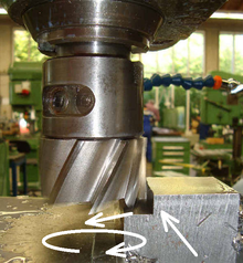
A line drawing showing some basic concepts of speeds and feeds in the context of lathe work. The angular velocity of the workpiece (rev/min) is called the "spindle speed" by machinists. Its tangential linear equivalent at the workpiece surface (m/min or sfm) is called the "cutting speed", "surface speed", or simply the "speed" by machinists. The "feeds" may be for the X-axis or the Z-axis (typically mm/rev or inch/rev for lathe work; sometimes measured as mm/min or inch/min). Notice that as the tool plunges closer to the workpiece's center, the same spindle speed will yield a decreasing surface (cutting) speed (because each rev represents a smaller circumferential distance, but takes the same amount of time). Most CNC lathes have constant surface speed to counteract that natural decrease, which speeds up the spindle as the tool plunges in.Photo of a milling cutter during a cutting operation. Arrows show the vectors of various velocities collectively known as speeds and feeds. The circular arrow represents the angular velocity of the spindle (rev/min), called the "spindle speed" by machinists. The tangential arrow represents the tangential linear velocity (m/min or sfm) at the outer diameter of the cutter, called the "cutting speed", "surface speed", or simply the "speed" by machinists. The arrow colinear with the slot that has been milled represents the linear velocity at which the cutter is advanced laterally (usually mm/min or inch/min for milling; may also be measured as mm/rev or inch/rev). This velocity is called the "feed" by machinists.
The phrase speeds and feeds or feeds and speeds refers to two separate velocities in machine tool practice, cutting speed and feed rate. They are often considered as a pair because of their combined effect on the cutting process. Each, however, can also be considered and analyzed in its own right.
Cutting speed (also called surface speed or simply speed) is the speed difference (relative velocity) between the cutting tool and the surface of the workpiece it is operating on. It is expressed in units of distance across the workpiece surface per unit of time, typically surface feet per minute (sfm) or meters per minute (m/min).[1]Feed rate (also often styled as a solid compound, feedrate, or called simply feed) is the relative velocity at which the cutter is advanced along the workpiece; its vector is perpendicular to the vector of cutting speed. Feed rate units depend on the motion of the tool and workpiece; when the workpiece rotates (e.g., in turning and boring), the units are almost always distance per spindle revolution (inches per revolution [in/rev or ipr] or millimeters per revolution [mm/rev]).[2] When the workpiece does not rotate (e.g., in milling), the units are typically distance per time (inches per minute [in/min or ipm] or millimeters per minute [mm/min]), although distance per revolution or per cutter tooth are also sometimes used.[2]
If variables such as cutter geometry and the rigidity of the machine tool and its tooling setup could be ideally maximized (and reduced to negligible constants), then only a lack of power (that is, kilowatts or horsepower) available to the spindle would prevent the use of the maximum possible speeds and feeds for any given workpiece material and cutter material. Of course, in reality those other variables are dynamic and not negligible, but there is still a correlation between power available and feeds and speeds employed. In practice, lack of rigidity is usually the limiting constraint.
The phrases "speeds and feeds" or "feeds and speeds" have sometimes been used metaphorically to refer to the execution details of a plan, which only skilled technicians (as opposed to designers or managers) would know.
Cutting speed
Cutting speed may be defined as the rate at the workpiece surface, irrespective of the machining operation used. A cutting speed for mild steel of 100ft/min is the same whether it is the speed of the cutter passing over the workpiece, such as in a turning operation, or the speed of the cutter moving past a workpiece, such as in a milling operation. The cutting conditions will affect the value of this surface speed for mild steel.
Schematically, speed at the workpiece surface can be thought of as the tangential speed at the tool-cutter interface, that is, how fast the material moves past the cutting edge of the tool, although "which surface to focus on" is a topic with several valid answers. In drilling and milling, the outside diameter of the tool is the widely agreed surface. In turning and boring, the surface can be defined on either side of the depth of cut, that is, either the starting surface or the ending surface, with neither definition being "wrong" as long as the people involved understand the difference. An experienced machinist summed this up succinctly as "the diameter I am turning from" versus "the diameter I am turning to."[3] He uses the "from", not the "to", and explains why, while acknowledging that some others do not. The logic of focusing on the largest diameter involved (OD of drill or end mill, starting diameter of turned workpiece) is that this is where the highest tangential speed is, with the most heat generation, which is the main driver of tool wear.[3]
There will be an optimum cutting speed for each material and set of machining conditions, and the spindle speed (RPM) can be calculated from this speed. Factors affecting the calculation of cutting speed are:
The material being machined (steel, brass, tool steel, plastic, wood) (see table below)
The economical life of the cutter (the cost to regrind or purchase new, compared to the quantity of parts produced)
Cutting speeds are calculated on the assumption that optimum cutting conditions exist. These include:
Metal removal rate (finishing cuts that remove a small amount of material may be run at increased speeds)
Full and constant flow of cutting fluid (adequate cooling and chip flushing)
Rigidity of the machine and tooling setup (reduction in vibration or chatter)
Continuity of cut (as compared to an interrupted cut, such as machining square section material in a lathe)
Condition of material (mill scale, hard spots due to white cast iron forming in castings)
The cutting speed is given as a set of constants that are available from the material manufacturer or supplier. The most common materials are available in reference books or charts, but will always be subject to adjustment depending on the cutting conditions. The following table gives the cutting speeds for a selection of common materials under one set of conditions. The conditions are a tool life of 1 hour, dry cutting (no coolant), and at medium feeds, so they may appear to be incorrect depending on circumstances. These cutting speeds may change if, for instance, adequate coolant is available or an improved grade of HSS is used (such as one that includes [cobalt]).
Cutting speeds for various materials using a plain high-speed steel cutter
The machinability rating of a material attempts to quantify the machinability of various materials. It is expressed as a percentage or a normalized value. The American Iron and Steel Institute (AISI) determined machinability ratings for a wide variety of materials by running turning tests at 180 surface feet per minute (sfpm). It then arbitrarily assigned 160 Brinell B1112 steel a machinability rating of 100%. The machinability rating is determined by measuring the weighed averages of the normal cutting speed, surface finish, and tool life for each material. Note that a material with a machinability rating less than 100% would be more difficult to machine than B1112 and material and a value more than 100% would be easier.
Machinability ratings can be used in conjunction with the Taylor tool life equation, VTn = C in order to determine cutting speeds or tool life. It is known that B1112 has a tool life of 60 minutes at a cutting speed of 100 sfpm. If a material has a machinability rating of 70%, it can be determined, with the above knowns, that in order to maintain the same tool life (60 minutes), the cutting speed must be 70 sfpm (assuming the same tooling is used).
When calculating for copper alloys, the machine rating is arrived at by assuming the 100 rating of 600 SFM. For example, phosphorus bronze (grades A–D) has a machinability rating of 20. This means that phosphor bronze runs at 20% the speed of 600 SFM or 120 SFM. However, 165 SFM is generally accepted as the basic 100% rating for "grading steels".[11] Formula Cutting Speed (V)= [πDN]/1000 m/min Where D=Diameter of Workpiece in meter or millimeter N=Spindle Speed in rpm
The spindle speed is the rotational frequency of the spindle of the machine, measured in revolutions per minute (RPM). The preferred speed is determined by working backward from the desired surface speed (sfm or m/min) and incorporating the diameter (of workpiece or cutter).
Excessive spindle speed will cause premature tool wear, breakages, and can cause tool chatter, all of which can lead to potentially dangerous conditions. Using the correct spindle speed for the material and tools will greatly enhance tool life and the quality of the surface finish.
For a given machining operation, the cutting speed will remain constant for most situations; therefore the spindle speed will also remain constant. However, facing, forming, parting off, and recess operations on a lathe or screw machine involve the machining of a constantly changing diameter. Ideally, this means changing the spindle speed as the cut advances across the face of the workpiece, producing constant surface speed (CSS). Mechanical arrangements to effect CSS have existed for centuries, but they were never applied commonly to machine tool control. In the pre-CNC era, the ideal of CSS was ignored for most work. For unusual work that demanded it, special pains were taken to achieve it. The introduction of CNC-controlled lathes has provided a practical, everyday solution via automated CSS Machining Process Monitoring and Control. By means of the machine's software and variable speed electric motors, the lathe can increase the RPM of the spindle as the cutter gets closer to the center of the part.
Grinding wheels are designed to be run at a maximum safe speed, the spindle speed of the grinding machine may be variable but this should only be changed with due attention to the safe working speed of the wheel. As a wheel wears it will decrease in diameter, and its effective cutting speed will be reduced. Some grinders have the provision to increase the spindle speed, which corrects for this loss of cutting ability; however, increasing the speed beyond the wheels rating will destroy the wheel and create a serious hazard to life and limb.
Generally speaking, spindle speeds and feed rates are less critical in woodworking than metalworking. Most woodworking machines including power saws such as circular saws and band saws, jointers, Thickness planers rotate at a fixed RPM. In those machines, cutting speed is regulated through the feed rate. The required feed rate can be extremely variable depending on the power of the motor, the hardness of the wood or other material being machined, and the sharpness of the cutting tool.
In woodworking, the ideal feed rate is one that is slow enough not to bog down the motor, yet fast enough to avoid burning the material. Certain woods, such as black cherry and maple are more prone to burning than others. The right feed rate is usually obtained by "feel" if the material is hand fed, or by trial and error if a power feeder is used. In thicknessers (planers), the wood is usually fed automatically through rubber or corrugated steel rollers. Some of these machines allow varying the feed rate, usually by changing pulleys. A slower feed rate usually results in a finer surface as more cuts are made for any length of wood.
Spindle speed becomes important in the operation of routers, spindle moulders or shapers, and drills. Older and smaller routers often rotate at a fixed spindle speed, usually between 20,000 and 25,000 rpm. While these speeds are fine for small router bits, using larger bits, say more than 1-inch (25mm) or 25 millimeters in diameter, can be dangerous and can lead to chatter. Larger routers now have variable speeds and larger bits require slower speed. Drilling wood generally uses higher spindle speeds than metal, and the speed is not as critical. However, larger diameter drill bits do require slower speeds to avoid burning.
Cutting feeds and speeds, and the spindle speeds that are derived from them, are the ideal cutting conditions for a tool. If the conditions are less than ideal then adjustments are made to the spindle's speed, this adjustment is usually a reduction in RPM to the closest available speed, or one that is deemed (through knowledge and experience) to be correct.
Some materials, such as machinable wax, can be cut at a wide variety of spindle speeds, while others, such as stainless steel require much more careful control as the cutting speed is critical, to avoid overheating both the cutter and workpiece. Stainless steel is one material that hardens very easily under cold working, therefore insufficient feed rate or incorrect spindle speed can lead to less than ideal cutting conditions as the work piece will quickly harden and resist the tool's cutting action. The liberal application of cutting fluid can improve these cutting conditions; however, the correct selection of speeds is the critical factor.
Spindle speed calculations
Most metalworking books have nomograms or tables of spindle speeds and feed rates for different cutters and workpiece materials; similar tables are also likely available from the manufacturer of the cutter used.
The spindle speeds may be calculated for all machining operations once the SFM or MPM is known. In most cases, we are dealing with a cylindrical object such as a milling cutter or a workpiece turning in a lathe so we need to determine the speed at the periphery of this round object. This speed at the periphery (of a point on the circumference, moving past a stationary point) will depend on the rotational speed (RPM) and diameter of the object.
One analogy would be a skateboard rider and a bicycle rider travelling side by side along the road. For a given surface speed (the speed of this pair along the road) the rotational speed (RPM) of their wheels (large for the skater and small for the bicycle rider) will be different. This rotational speed (RPM) is what we are calculating, given a fixed surface speed (speed along the road) and known values for their wheel sizes (cutter or workpiece).
The following formulae[12] may be used to estimate this value.
Approximation
The exact RPM is not always needed, a close approximation will work. For instance, a machinist may want to take the value of to be 3 if performing calculations by hand.
e.g. for a cutting speed of 100ft/min (a plain HSS steel cutter on mild steel) and diameter of 10inches (the cutter or the work piece)
and, for an example using metric values, where the cutting speed is 30 m/min and a diameter of 10mm (0.01 m),
Accuracy
However, for more accurate calculations, and at the expense of simplicity, this formula can be used:
and using the same example
and using the same example as above
where:
RPM is the rotational speed of the cutter or workpiece.
Speed is the recommended cutting speed of the material in meters/minute or feet/min
Diameter in millimeters or inches.
Feed rate
Feed rate is the velocity at which the cutter is fed, that is, advanced against the workpiece. It is expressed in units of distance per revolution for turning and boring (typically inches per revolution [ipr] or millimeters per revolution). It can be expressed thus for milling also, but it is often expressed in units of distance per time for milling (typically inches per minute [ipm] or millimeters per minute), with considerations of how many teeth (or flutes) the cutter has then determined what that means for each tooth.
Feed rate is dependent on the:
Type of tool (a small drill or a large drill, high speed or carbide, a boxtool or recess, a thin form tool or wide form tool, a slide knurl or a turret straddle knurl).
Surface finish desired.
Power available at the spindle (to prevent stalling of the cutter or workpiece).
Rigidity of the machine and tooling setup (ability to withstand vibration or chatter).
Strength of the workpiece (high feed rates will collapse thin wall tubing)
Characteristics of the material being cut, chip flow depends on material type and feed rate. The ideal chip shape is small and breaks free early, carrying heat away from the tool and work.
Cut Width. Any time the width of cut is less than half the diameter, a geometric phenomenon called Chip Thinning reduces the actual chipload. Feedrates need to be increased to offset the effects of chip thinning, both for productivity and to avoid rubbing which reduces tool life.
When deciding what feed rate to use for a certain cutting operation, the calculation is fairly straightforward for single-point cutting tools, because all of the cutting work is done at one point (done by "one tooth", as it were). With a milling machine or jointer, where multi-tipped/multi-fluted cutting tools are involved, then the desired feed rate becomes dependent on the number of teeth on the cutter, as well as the desired amount of material per tooth to cut (expressed as chip load). The greater the number of cutting edges, the higher the feed rate permissible: for a cutting edge to work efficiently it must remove sufficient material to cut rather than rub; it also must do its fair share of work.
The ratio of the spindle speed and the feed rate controls how aggressive the cut is, and the nature of the swarf formed.
Formula to determine feed rate
This formula[13] can be used to figure out the feed rate that the cutter travels into or around the work. This would apply to cutters on a milling machine, drill press and a number of other machine tools. This is not to be used on the lathe for turning operations, as the feed rate on a lathe is given as feed per revolution.
Where:
FR = the calculated feed rate in inches per minute or mm per minute.
RPM = is the calculated speed for the cutter.
T = Number of teeth on the cutter.
CL = The chip load or feed per tooth. This is the size of chip that each tooth of the cutter takes.
Depth of cut
Cutting speed and feed rate come together with depth of cut to determine the material removal rate, which is the volume of workpiece material (metal, wood, plastic, etc.) that can be removed per time unit.
Interrelationship of theory and practice
Speed-and-feed selection is analogous to other examples of applied science, such as meteorology or pharmacology, in that the theoretical modeling is necessary and useful but can never fully predict the reality of specific cases because of the massively multivariate environment. Just as weather forecasts or drug dosages can be modeled with fair accuracy, but never with complete certainty, machinists can predict with charts and formulas the approximate speed and feed values that will work best on a particular job, but cannot know the exact optimal values until running the job. In CNC machining, usually the programmer programs speeds and feedrates that are as maximally tuned as calculations and general guidelines can supply. The operator then fine-tunes the values while running the machine, based on sights, sounds, smells, temperatures, tolerance holding, and tool tip lifespan. Under proper management, the revised values are captured for future use, so that when a program is run again later, this work need not be duplicated.
As with meteorology and pharmacology, however, the interrelationship of theory and practice has been developing over decades as the theory part of the balance becomes more advanced thanks to information technology. For example, an effort called the Machine Tool Genome Project is working toward providing the computer modeling (simulation) needed to predict optimal speed-and-feed combinations for particular setups in any internet-connected shop with less local experimentation and testing.[14] Instead of the only option being the measuring and testing of the behavior of its own equipment, it will benefit from others' experience and simulation; in a sense, rather than 'reinventing a wheel', it will be able to 'make better use of existing wheels already developed by others in remote locations'.
Academic research examples
Speeds and feeds have been studied scientifically since at least the 1890s. The work is typically done in engineering laboratories, with the funding coming from three basic roots: corporations, governments (including their militaries), and universities. All three types of institution have invested large amounts of money in the cause, often in collaborative partnerships. Examples of such work are highlighted below.
"Following World War II, many new alloys were developed. New standards were needed to increase [U.S.] American productivity. Metcut Research Associates, with technical support from the Air Force Materials Laboratory and the Army Science and Technology Laboratory, published the first Machining Data Handbook in 1966. The recommended speeds and feeds provided in this book were the result of extensive testing to determine optimum tool life under controlled conditions for every material of the day, operation and hardness."[3]
A study on the effect of the variation of cutting parameters in the surface integrity in turning of an AISI 304 stainless steel revealed that the feed rate has the greatest impairing effect on the quality of the surface, and that besides the achievement of the desired roughness profile, it is necessary to analyze the effect of speed and feed on the creation of micropits and microdefects on the machined surface.[17] Moreover, they found that the conventional empirical relation that relates feed rate to roughness value does not fit adequately for low cutting speeds.
Related Research Articles
A lathe is a machine tool that rotates a workpiece about an axis of rotation to perform various operations such as cutting, sanding, knurling, drilling, deformation, facing, and turning, with tools that are applied to the workpiece to create an object with symmetry about that axis.
Metalworking is the process of shaping and reshaping metals to create useful objects, parts, assemblies, and large scale structures. As a term it covers a wide and diverse range of processes, skills, and tools for producing objects on every scale: from huge ships, buildings, and bridges down to precise engine parts and delicate jewelry.
Machining is a manufacturing process whereby a desired shape or part is achieved by the controlled removal of material from a larger piece of raw material by cutting; most often performed with metal material. These processes are collectively called subtractive manufacturing, which utilizes machine tools, in contrast to additive manufacturing, which uses controlled addition of material.
Drill bits are cutting tools used in a drill to remove material to create holes, almost always of circular cross-section. Drill bits come in many sizes and shapes and can create different kinds of holes in many different materials. In order to create holes drill bits are usually attached to a drill, which powers them to cut through the workpiece, typically by rotation. The drill will grasp the upper end of a bit called the shank in the chuck.
Drilling is a cutting process where a drill bit is spun to cut a hole of circular cross-section in solid materials. The drill bit is usually a rotary cutting tool, often multi-point. The bit is pressed against the work-piece and rotated at rates from hundreds to thousands of revolutions per minute. This forces the cutting edge against the work-piece, cutting off chips (swarf) from the hole as it is drilled.
A collet is a segmented sleeve, band or collar. One of the two radial surfaces of a collet is usually tapered and the other is cylindrical. The term collet commonly refers to a type of chuck that uses collets to hold either a workpiece or a tool but has other mechanical applications.
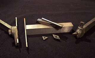
In machining, a tool bit is a non-rotary cutting tool used in metal lathes, shapers, and planers. Such cutters are also often referred to by the set-phrase name of single-point cutting tool, as distinguished from other cutting tools such as a saw or water jet cutter. The cutting edge is ground to suit a particular machining operation and may be resharpened or reshaped as needed. The ground tool bit is held rigidly by a tool holder while it is cutting.
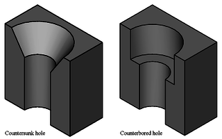
In manufacturing, a countersink is a conical hole cut into a manufactured object, or the cutter used to cut such a hole. A common use is to allow the head of a countersunk bolt, screw or rivet, when placed in the hole, to sit flush with or below the surface of the surrounding material. A countersink may also be used to remove the burr left from a drilling or tapping operation, thereby improving the finish of the product and removing any hazardous sharp edges.
Turning is a machining process in which a cutting tool, typically a non-rotary tool bit, describes a helix toolpath by moving more or less linearly while the workpiece rotates.
Milling cutters are cutting tools typically used in milling machines or machining centres to perform milling operations. They remove material by their movement within the machine or directly from the cutter's shape.
A lathe center, often shortened to center, is a tool that has been ground to a point to accurately position a workpiece on an axis. They usually have an included angle of 60°, but in heavy machining situations an angle of 75° is used.
In machining, a metal lathe or metalworking lathe is a large class of lathes designed for precisely machining relatively hard materials. They were originally designed to machine metals; however, with the advent of plastics and other materials, and with their inherent versatility, they are used in a wide range of applications, and a broad range of materials. In machining jargon, where the larger context is already understood, they are usually simply called lathes, or else referred to by more-specific subtype names. These rigid machine tools remove material from a rotating workpiece via the movements of various cutting tools, such as tool bits and drill bits.
In machining, boring is the process of enlarging a hole that has already been drilled by means of a single-point cutting tool, such as in boring a gun barrel or an engine cylinder. Boring is used to achieve greater accuracy of the diameter of a hole, and can be used to cut a tapered hole. Boring can be viewed as the internal-diameter counterpart to turning, which cuts external diameters.
In the context of machining, a cutting tool or cutter is typically a hardened metal tool that is used to cut, shape, and remove material from a workpiece by means of machining tools as well as abrasive tools by way of shear deformation. The majority of these tools are designed exclusively for metals.
Surface feet per minute is the combination of a physical quantity and an imperial and American customary unit. It is defined as the number of linear feet that a location on a rotating component travels in one minute. Its most common use is in the measurement of cutting speed in machining. It is a unit of velocity that describes how fast the cutting edge of the cutting tool travels. It correlates directly to the machinability of the workpiece material and the hardness of the cutting tool material. It relates to spindle speed via variables such as cutter diameter or workpiece diameter.
Grinding is a type of abrasive machining process which uses a grinding wheel as cutting tool.
Bar stock, also (colloquially) known as blank, slug or billet, is a common form of raw purified metal, used by industry to manufacture metal parts and products. Bar stock is available in a variety of extrusion shapes and lengths. The most common shapes are round, rectangular, square and hexagonal. A bar is characterised by an "enclosed invariant convex cross-section", meaning that pipes, angle stock and objects with varying diameter are not considered bar stock.
Arbor milling is a cutting process which removes material via a multi-toothed cutter. An arbor mill is a type of milling machine characterized by its ability to rapidly remove material from a variety of materials. This milling process is not only rapid but also versatile.
Milling is the process of machining using rotary cutters to remove material by advancing a cutter into a workpiece. This may be done by varying directions on one or several axes, cutter head speed, and pressure. Milling covers a wide variety of different operations and machines, on scales from small individual parts to large, heavy-duty gang milling operations. It is one of the most commonly used processes for machining custom parts to precise tolerances.
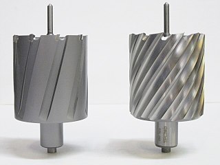
An annular cutter is a form of core drill used to create holes in metal. An annular cutter, named after the annulus shape, cuts only a groove at the periphery of the hole and leaves a solid core or slug at the center.
↑ Shen, C. H. (1996-12-15). "The importance of diamond coated tools for agile manufacturing and dry machining". Surface and Coatings Technology. 86–87: 672–677. doi:10.1016/S0257-8972(96)02969-6. ISSN0257-8972.
This page is based on this Wikipedia article Text is available under the CC BY-SA 4.0 license; additional terms may apply. Images, videos and audio are available under their respective licenses.