The 4-2-0 wheel arrangement type was common on United States railroads from the 1830s through the 1850s. The first 4-2-0 to be built was the Experiment, later named Brother Jonathan, for the Mohawk and Hudson Railroad in 1832. It was built by the West Point Foundry based on a design by John B. Jervis. Having little else to reference, the manufacturers patterned the boiler and valve gear after locomotives built by Robert Stephenson of England. A few examples of Stephenson locomotives were already in operation in America, so engineers did not have to travel too far to get their initial ideas.
In England, the 4-2-0 was developed around 1840 from the 2-2-2 design of Stephenson's first Long Boiler locomotive, which he had altered to place two pairs of wheels at the front to improve stability, with the outside cylinders between them.
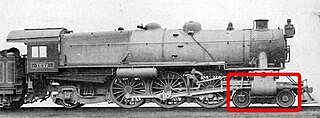
In the United States, the design was a modification of the 0-4-0 design, then in common use. The 0-4-0 proved to be too rigid for the railroads of the day, often derailing on the tight curves and rapid elevation changes of early American railroads. For the 4-2-0, Jervis introduced a four-wheel leading truck under the locomotive's smokebox. It swiveled independently from the main frame of the locomotive, in contrast to the English 4-2-0 engines which had rigid frames. The pistons powered a single driving axle at the rear of the locomotive, just behind the firebox. This design resulted in a much more stable locomotive which was able to guide itself into curves more easily than the 0-4-0.[1][2]
This design proved so effective on American railroads that many of the early 0-4-0s were rebuilt as 4-2-0s. The 4-2-0 excelled in its ability to stay on the track, especially those with the single driving axles behind the firebox, whose main virtue was stability. However, with only one driving axle behind the firebox, the locomotive's weight was spread over a small proportion of powered wheels, which substantially reduced its adhesive weight. On 4-2-0 locomotives which had the driving axle in front of the firebox, adhesive weight was increased. While this plan placed more of the locomotive's weight on the driving axle, it reduced the weight on the leading truck which made it more prone to derailments.[1][2]
One possible solution was patented in 1834 by E.L. Miller and used extensively by Matthias W. Baldwin. It worked by raising a pair of levers to attach the tender frame to an extension of the engine frame, which transferred some weight from the tender to the locomotive frame and increased the adhesive weight. An automatic version was patented in 1835 by George E. Sellers and was used extensively by locomotive builder William Norris after he obtained rights to it. This system used a beam whose fulcrum was the driving axle. On flat and level surfaces, the beam would be slightly raised, but upon starting or on grades, the resistance made the beam assume a horizontal position which caused the locomotive to tip upward.[1][2]
A more practical solution, first put into production by Norris, relocated the driving axle to a location on the frame in front of the locomotive's firebox. This was done because Baldwin refused to grant rights to Norris to use his patented "half-crank" arrangement. Cantilevering the weight of the firebox and the locomotive crew behind the driving axle placed more weight on the driving axle without substantially reducing the weight on the leading truck. However Norris's design led to a shorter wheelbase, which tended to offset any gains in tractive force on the driving axle by reducing the locomotive's overall stability. A number of Norris locomotives were imported into England for use on the Birmingham and Bristol Railway since, because of the challenges presented by the Lickey Incline, British manufacturers declined to supply.[1][2]
Once steel became available, greater rotational speeds became possible with multiple smaller coupled wheels. Five years after new locomotive construction began with the 0-4-0Best Friend of Charleston of 1831, at the US West Point Foundry, the first 4-4-0 locomotive was designed by Henry R. Campbell, at the time the chief engineer for the Philadelphia, Germantown and Norristown Railway. Campbell received a patent for the design in February 1836 and soon set to work building the first 4-4-0. Campbell's 4-4-0 was a giant among locomotives for the time. Its cylinders were 14in ×16in (356mm ×406mm), had 54in (1,372mm) diameter driving wheels, a 90psi (620kPa) boiler and weighed 12 short tons (10.9t). Campbell's locomotive was estimated to be able to pull a train of 450 short tons (410t) at 15mph (24km/h) on level track, outperforming the strongest of Baldwin's 4-2-0s in tractive effort by about 63%. However, the frame and driving gear of his locomotive proved to be too rigid for the railroads of the time, which caused Campbell's prototype to be derailment-prone.[1][2]
As the 1840s approached and more American railroads began to experiment with the new 4-4-0 locomotive type, the 4-2-0 fell out of favor since it was not as capable when pulling a load. 4-2-0s continued to be built into the 1850s, but their use was restricted to light-duty trains since, by this time, most railroads had found them unsuitable for regular work.[1][2]
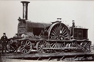
In England four-coupled and six-coupled engines performed well with freight work. However, the aim for passenger work was greater speed. Because of the fragile cast iron connecting rods, "singles" continued to be used, with the largest driving wheels possible.
For unclear reasons, British manufacturers did not take up the idea of mounting the forward wheels on a bogie for some years. There were possibly fears about their stability and with a long rigid frame, greater speed was achieved, albeit at the cost of a very rough ride and damage to the track. The culmination of this approach was seen in the Crampton locomotive where, to make the driving wheels as large as possible, they were mounted behind the firebox.[1][2][3]
Nevertheless, this wheel arrangement, the 2-2-0 wheel arrangement and the 4-4-0 wheel arrangement are the most popular wheel arrangements in all of TV shows, cartoons, video games, toys and more.
In 1923, the South African Railways conducted trials with a prototype petrol-paraffin powered road-rail tractor and, in 1924, placed at least two Dutton steam road-rail tractors in service on the new 2ft (610mm) narrow gauge line between Naboomspruit and Singlewood in Transvaal. The petrol-paraffin prototype and one of the latter had a 4-2-0 wheel arrangement.[4][5]
The prototype was a modified Dennis tractor which was fitted with a removable bogie between the front wheels to lift them high enough to prevent ground contact. A ball pin on the bogie fit into a socket in the front axle, and the bogie could easily be removed or replaced by running the tractor up a pair of ramps, placed on both sides of the track.[4][6][7][8]
The production model was a modified Yorkshire steam tractor, fitted with jacks at the front to allow a separate bogie to be manoeuvred into position underneath the front axle to guide it on the rails. Without the bogie, the vehicle could still be driven on ordinary roads and had the advantage of being able to be detached and run around the train, without requiring special loops for that purpose. For reversing on the track, as when shunting, the rear wheels were modified to be steerable.[5][9]
A tank locomotive is a steam locomotive which carries its water in one or more on-board water tanks, instead of a more traditional tender. Most tank engines also have bunkers to hold fuel; in a tender-tank locomotive a tender holds some or all of the fuel, and may hold some water also.
Under the Whyte notation for the classification of steam locomotives, 2-10-0 represents the wheel arrangement of two leading wheels on one axle, ten powered and coupled driving wheels on five axles, and no trailing wheels. This arrangement was often named Decapod, especially in the United States, although this name was sometimes applied to locomotives of 0-10-0 "Ten-Coupled" arrangement, particularly in the United Kingdom. Notable German locomotives of this type include the war locomotives of Class 52.
Main components found on a typical steam locomotive include:
4-4-0, in the Whyte notation, denotes a steam locomotive with a wheel arrangement of four leading wheels on two axles, four powered and coupled driving wheels on two axles, and no trailing wheels.
A 4-6-0 steam locomotive, under the Whyte notation for the classification of steam locomotives by wheel arrangement, has four leading wheels on two axles in a leading bogie and six powered and coupled driving wheels on three axles with the absence of trailing wheels.
In the Whyte notation, a 6-2-0 is a railroad steam locomotive that has an unpowered three-axle leading truck followed by a single powered driving axle. This wheel arrangement is associated with the Crampton locomotive type, and in the USA the single class were sometimes referred to as Cramptons.
Under the Whyte notation for the classification of steam locomotives, 4-2-2 represents the wheel arrangement of four leading wheels on two axles, two powered driving wheels on one axle, and two trailing wheels on one axle.
In the Whyte notation for the classification of steam locomotive wheel arrangement, an 0-4-4-0 is a locomotive with no leading wheels, two sets of four driving wheels, and no trailing wheels. The arrangement is chosen to give the articulation of a locomotive with only the short rigid wheelbase of an 0-4-0, but with its weight spread across eight wheels, and with all the weight carried on the driving wheels; effectively a flexible 0-8-0. Articulated examples were constructed as Mallet, Meyer, BMAG and Double Fairlie locomotives and also as geared locomotives such as Shay, Heisler, and Climax types. A similar configuration was used on some Garratt locomotives, but it is referred to as 0-4-0+0-4-0. In the electric and diesel eras, the Bo-Bo is comparable and closest to the Meyer arrangement of two swivelling bogies.
The GWR 4100 Class was a class of steam locomotives in the Great Western Railway (GWR) of the United Kingdom.
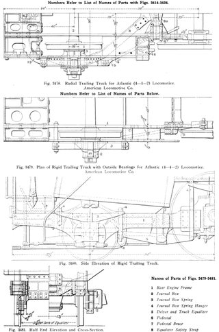
On a steam locomotive, a trailing wheel or trailing axle is generally an unpowered wheel or axle (wheelset) located behind the driving wheels. The axle of the trailing wheels is usually located in a trailing truck. On some large locomotives, a booster engine was mounted on the trailing truck to provide extra tractive effort when starting a heavy train and at low speeds on gradients.
Under the Whyte notation for the classification of steam locomotives, 4-2-4 represents the wheel arrangement of four leading wheels on two axles, two powered driving wheels on one axle, and four trailing wheels on two axles.
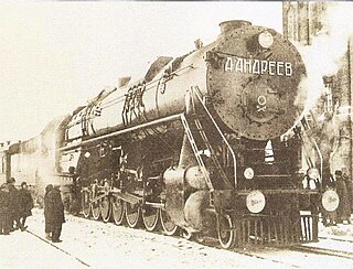
The AA20 was a one-off steam locomotive constructed by the Soviet Union.
B-B and Bo-Bo are the Association of American Railroads (AAR) and British classifications of wheel arrangement for railway locomotives with four axles in two individual bogies. They are equivalent to the B′B′ and Bo′Bo′ classifications in the UIC system. The arrangement of two, two-axled, bogies is a common wheel arrangement for modern electric and diesel locomotives.
A lateral motion device is a mechanism used in some railroad locomotives which permits the axles to move sideways relative to the frame. The device allows easier cornering.
The Bury Bar Frame locomotive was an early type of steam locomotive, developed at the Liverpool works of Edward Bury and Company, later named Bury, Curtis, and Kennedy in 1842. By the 1830s, the railway locomotive had evolved into three basic types - those developed by Robert Stephenson, Timothy Hackworth and Edward Bury.
The leading wheel or leading axle or pilot wheel of a steam locomotive is an unpowered wheel or axle located in front of the driving wheels. The axle or axles of the leading wheels are normally located on a leading truck. Leading wheels are used to help the locomotive negotiate curves and to support the front portion of the boiler.
The South African Railways Class 6Z 2-6-4 of 1901 was a steam locomotive from the pre-Union era in the Cape of Good Hope.
The South African Railways Dutton road-rail tractors of 1923 were road-rail steam tractors.
Henry Roe Campbell was an American surveyor and civil engineer. Campbell contributed to American railroading and bridge-building in the first half of the 19th century. Campbell patented his 4-4-0 design in February 1836, just a few months before the patent law was changed to require that claims include proof of originality or novelty.
Under the Whyte notation for the classification of steam locomotives, 0-6-6 represents the wheel arrangement of no leading wheels, six powered and coupled driving wheels on three axles and six trailing wheels on three axles. All locomotives with this wheel arrangement were tank locomotives; no 0-6-6 tender locomotives were recorded.
1 2 3 4 5 6 7 White, John H. Jr. (1968). A history of the American locomotive; its development: 1830–1880. New York, NY: Dover Publications. ISBN0-486-23818-0.
↑ Comstock, Henry B. (1971). The Iron Horse. Toronto, Canada: Fitzhenry & Whiteside Limited.
1 2 Espitalier, T.J.; Day, W.A.J. (1945). The Locomotive in South Africa - A Brief History of Railway Development. Chapter VII - South African Railways (Continued). South African Railways and Harbours Magazine, October 1945. pp. 782-783.
1 2 Paxton, Leith; Bourne, David (1985). Locomotives of the South African Railways (1sted.). Cape Town: Struik. pp.118–119. ISBN0869772112.
This page is based on this Wikipedia article Text is available under the CC BY-SA 4.0 license; additional terms may apply. Images, videos and audio are available under their respective licenses.