Philosophy
The radio was called the "All American Five" because the design typically used five vacuum tubes, and comprised the majority of radios manufactured for home use in the USA and Canada in the tube era.
They were manufactured in the millions by hundreds of manufacturers from the 1930s onward, and the last examples were made in Japan. The heaters of the tubes were connected in series, all requiring the same current, but with different voltages across them. The standard line up of tubes were designed so that the total rated voltage of the five tubes was 121 volts, slightly more than the electricity supply voltage of 110–117V. An extra dropper resistor was therefore not required. Transformerless designs had a metal chassis connected to one side of the power line, which was a dangerous electric shock hazard and required a thoroughly insulated cabinet. Transformerless radios could be powered by either AC or DC (consequently called AC/DC receivers)—DC supplies were still not uncommon. When operated on DC, they would only work if the plug was inserted with the correct polarity.
The philosophy of the design was simple: it had to be as cheap to make as possible. The design was optimized to provide good performance for the price. At least one radio manufacturer, Atwater Kent, preferred to go out of business rather than attempt to compete with 'midget' or low-cost AA5 designs. [4]
Many design tricks were used to reduce production costs of the five-tube radio. The heaters of all the vacuum tubes had to be rated to use the same current, so they could be operated in series from line voltage. The rectifier and audio output tube required more heater power, so dropped a larger voltage than the other tubes. In many designs the rectifier tube had a tap on the heater to power a dial light. The plate current was routed through that portion of the rectifier heater, in order to make up for the current diverted to the dial lamp. If the dial lamp failed, that part of the rectifier heater would have a larger current which could burn out the tube in a few months. Early radios had a resistor network to minimize the problem but this was soon eliminated as the cost of replacing the tube was not the manufacturer's problem. As with Christmas tree lights, if one tube heater failed, none of the tube heaters would operate.
The frequency mixer was of the pentagrid converter design to save the cost of a separate oscillator tube. The detector and first audio stage were provided by a dual diode/triode combination tube. When the detector/first audio tube contained a second diode, it could be used to provide automatic gain control (AGC), or AGC bias could be derived from the audio detector diode. [5]
Potential hazards of the design
Many early examples of the 'All-American Five' posed a shock hazard to users. Lacking a mains transformer, the chassis of the AA5 radio was directly connected to one side of the mains electric supply. The hazard was made worse because the on/off switch was often in the wire of the mains supply which was connected to the chassis, meaning that the chassis could be "hot" when the set was either 'on' or 'off', depending on which way the plug was inserted in the power outlet. Many power plugs had two identical pins, and could be plugged in either way round. The metal chassis securing screws were sometimes accessible from the outside of the Bakelite or wood case, and there were many examples of owners receiving a shock by making contact with these screws while handling a set. Ventilation holes could be large enough to allow children to poke their fingers, or metal objects, through. The same type of hazard was present in European AC/DC sets, at twice the voltage.
The hazard was eliminated from later sets by the use of an internal ground bus connected to the chassis by an isolation network. Underwriters Laboratories required the adoption of the floating chassis, as isolation from the mains (the exact circuit and component values were not specified although the leakage current allowed was) to limit the shock to a "safe" current level. The chassis was maintained at RF ground (for shielding) by a bypass capacitor (typically 0.05 μF to 0.2 μF) usually with a resistor connected across it (typically 220 kΩ to 470 kΩ, although values as small as 22 kΩ were sometimes used or the resistor was simply omitted). [6] [7] Over the years, these paper capacitors often become leaky, and could allow sufficient current flow to give the user a shock.
Variations on the theme
Although four-, six-, and even a few rare eight-tube radios were produced, they were not common. The four-tube version with vacuum tube rectifier was of inferior performance, as they typically had no IF amplifier tube, although some four-tube designs with a selenium rectifier in place of the rectifier tube avoided this problem. The six-tube versions added either an RF amplifier tube, a push-pull audio power amplifier tube, or a beat frequency oscillator tube (to listen to Morse code or single-sideband modulation transmissions). However, these radios cost significantly more and sold in smaller quantities. The eight-tube versions cost even more, adding two or more of the features of the six-tube versions and sometimes an extra IF amplifier tube.
| # Tubes | RF Amp | BFO | Converter | IF Amp | Det/Pre-amp | Audio Amp | Rectifier |
|---|
| 4 | | | X | | X | X | X |
| 4 | | | X | X | X | X | (selenium) |
| 5 (standard) | | | X | X | X | X | X |
| 6 | X | | X | X | X | X | X |
| 6 | | | X | X | X | X X (push-pull) | X |
| 6 | | X | X | X | X | X | X |
| 8 | X | | X | X | X X (push-pull) | X X (push-pull) | X |
| 8 | X | | X | X X | X | X X (push-pull) | X |
| 8 | | X | X | X | X X (push-pull) | X X (push-pull) | X |
| 8 | X | X | X | X | X | X X (push-pull) | X |
|
Specific implementations
The basic design of the 'All-American Five' had its origins in low-cost sets produced in the early days of radio.
Early attempts
Radio manufacturers departed from the traditional heater voltages of 2.5, 5 and 6.3 volts to get a five tube combination that would operate as close as possible to 110–120 VAC line voltage. For the 1935 model year, designers were able to get a 5-tube heater string to total up to 78 volts. This meant that a dropping resistor or line ballast tube was needed to drop the remaining 35–42 volts. If a ballast tube was used, the radio would be marketed as a "6-tube" radio even though one was just a voltage dropping ballast. Other manufacturers used a "line cord resistor", a special AC cord made with resistance wire which replaced a power resistor in the radio chassis. These line cords tend to get warm to the touch after the radio was in use for a while.
During the 1935–36 model years examples of 5 tube (pre-octal base or prong tubes) series strings using 300 mA heaters were:
- Detector-Oscillator: 78
- Intermediate Frequency (IF): 78
- Second Detector and First Audio Amplifier: 77
- Power Amplifier: 43
- Rectifier: 25Z5
Later when newer tubes came out another variant was:
- Pentagrid Converter: 6A7
- Intermediate Frequency (IF): 78 or 6D6
- Second Detector and First Audio Amplifier: 75
- Power Amplifier: 43
- Rectifier: 25Z5
[8]
The very first set of metal tubes produced included 6-volt heater tubes that could be used to make a transformer-powered 6-tube radio. RCA released their first set of these metal octal tubes for this design in 1939, using 12.6-volt 150 mA heaters instead. The original design used the following tubes:
This series had the grids brought out as top caps on the signal tubes, and the 35Z4 did not have a provision for a dial light.
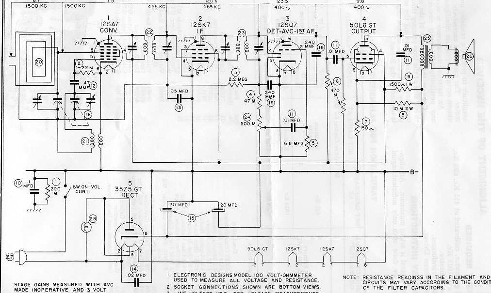
Single ended tube variant
AC/DC designs for 110–117V usually used 150 mA heater current.
The tube array in the early days of single ended octal tubes was:
- Converter: 12SA7
- IF amplifier: 12SK7
- Detector and first audio amplifier: 12SQ7
- Audio power output: 50L6
- Rectifier: 35Z5
These sets were first marketed in late 1939. Canadian sets would sometimes use a 35L6 in place of the 50L6, as parts of Canada used 110 volts as a design standard. Because areas near Niagara Falls had 25 Hz power, some Canadian sets had slightly larger filter capacitors.
The "Loctal" variant
The tube line up of the Loctal tubes was:
- Converter: 14Q7
- IF amplifier: 14A7
- Detector and first audio amplifier: 14B6
- Audio power output: 50A5
- Rectifier: 35Y4 or 35Z3
Miniature tubes
After the Second World War the set was redesigned to use miniature 7-pin tubes and the line up became:
- Converter: 12BE6
- IF amplifier: 12BA6
- Detector and first audio amplifier: 12AV6 or 12AT6
- Audio power output: 50C5 or the less-common 50B5
- Rectifier: 35W4
The 50C5, introduced in 1948, is electrically identical to the 50B5, but has a revised pinout to address concerns that high peak voltage between 4 (heater) and 5 (anode) would promote socket breakdown. [1]
In the postwar period, some makers built sets with a mixture of miniature, octal, and loctal types.
"Power-Saver" version
Another low-power variation changed the tube heaters to run on 100 milliamperes rather than 150 milliamperes. These tubes took a little longer to warm up:
- Converter: 18FX6
- IF amplifier: 18FW6
- Detector and first audio amplifier: 18FY6
- Audio power output: 32ET5 or 34GD5
- Rectifier: 36AM3
The voltage distribution has changed around the tube heaters but the total is still a little more than the 120 volt mains supply. This line-up is for an Admiral radio.
Farm radio
A "farm radio" modification (usually done at the point of sale) allowed an AA5 to run off 32 volts DC, commonly generated by farm windmills. With a relatively simple rewiring, the tube heaters could be put in series-parallel to run off 32 volts, with the three twelve-volt heaters in series and a 25L6, 35L6 or 43 in parallel; the tubes would still function with the heater voltage somewhat out of specification. If run from a 32-volt supply the radio had a substantially reduced performance because the B+ voltage would only be 32 volts compared with 160–170 volts when operated from AC. With 32 volts on the plate, the radio tended to be insensitive. [9] Sometimes only the tube heater power was derived from a windmill, and dry batteries were retained for the plate voltage supply. The advantage was that the heaters were a high and continuous load on the battery, whereas the plate voltage battery drain was smaller and intermittent. Often a wet-cell rechargeable battery was used for tube heaters, recharged by a local garage or by exchanging with a vehicle battery.
Many 32-volt farm radios were factory-built for the purpose. They usually had two type 48 power tetrodes that could operate with B+ voltages as low as 28 volts. The type 48 pairs were parallel connected, or connected in push–pull. Some factory 32-volt radios used an electromechanical vibrator power supply to provide increased voltage. Vibrator power supplies could also be made to work from a 6 volt supply from a dedicated wind-charger or from a car battery borrowed from a farm vehicle.
Battery operated variants
A number of other versions of the set appeared, including some that did have a transformer, a version that operated in a motor vehicle off a 6-volt supply, using a vibrator to convert the 6V DC supply to AC which could feed a transformer with higher voltage output, and a version that operated from either dry batteries or the mains supply. The battery version commonly used tubes where the filament was heated by a single 1.5-volt dry cell and plate voltage was supplied by a (nominally) 90-volt battery.
One version, called a Three-way portable because it could be operated any of three ways: batteries, the AC line, or the DC line; typically had the following tube array:
- Converter: 1R5 (or 1L6 if the set was shortwave, such as the Zenith Trans-Oceanic)
- IF amplifier: 1U4
- Detector and first audio amplifier: 1U5
- Audio power output: 3V4
- Rectifier: 35W4, 117Z3, or a selenium rectifier
This version used a 7.5 V A battery and a 90 V B battery. Note that the A battery did not need to heat the rectifier tube because, when operating from the batteries, the rectifier was not needed.
When operating on batteries, this version had almost instant warmup because of the tubes used their filaments as cathodes. This setup was common on Motorola portable radios commonly resembling metal "lunch boxes".
Variations
Since the AA5 was a minimalist design, there was plenty of room for enhanced versions, resulting in an "AA6":
- A few sets added an extra 12SK7 as an RF or IF amplifier. This would require using a 35L6 to maintain the heater voltage.
- Or, another audio amplifier tube could be added for increased audio output. To keep the total heater voltage at around 120 V, the two output tubes would have to be 25 to 35-volt types, such as the 35L6 or 25L6.
There were even a few "AA4" designs, usually midget sets, only usable in strong-signal metropolitan areas, because most had no IF amplifier (although some replaced the rectifier tube with a selenium rectifier).
This page is based on this
Wikipedia article Text is available under the
CC BY-SA 4.0 license; additional terms may apply.
Images, videos and audio are available under their respective licenses.


