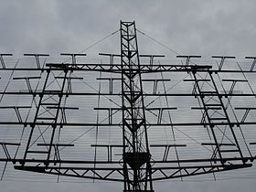
A common type of array antenna, a reflective array UHF television antenna. This example consists of eight dipoledriven elements mounted in front of a wire screen reflector. The X-shaped dipoles give it a wide bandwidth to cover both the VHF (174–216MHz) and UHF (470–700MHz) TV bands. It has a gain of 5dB VHF and 12dB UHF and an 18dB front-to-back ratio.Large planar array antenna of a VHF Russian mobile air defense radar, the Nebo-M. It consists of 175 folded dipole antennas. An early phased array, the antenna radiated a vertical fan-shaped beam which could be swept horizontally across the airspace in front of the antenna.
An antenna array (or array antenna) is a set of multiple connected antennas which work together as a single antenna, to transmit or receive radio waves. The individual antennas (called elements) are usually connected to a single receiver or transmitter by feedlines that feed the power to the elements in a specific phase relationship. The radio waves radiated by each individual antenna combine and superpose, adding together (interfering constructively) to enhance the power radiated in desired directions, and cancelling (interfering destructively) to reduce the power radiated in other directions. Similarly, when used for receiving, the separate radio frequency currents from the individual antennas combine in the receiver with the correct phase relationship to enhance signals received from the desired directions and cancel signals from undesired directions. More sophisticated array antennas may have multiple transmitter or receiver modules, each connected to a separate antenna element or group of elements.
An antenna array can achieve higher gain (directivity), that is a narrower beam of radio waves, than could be achieved by a single element. In general, the larger the number of individual antenna elements used, the higher the gain and the narrower the beam. Some antenna arrays (such as military phased array radars) are composed of thousands of individual antennas. Arrays can be used to achieve higher gain, to give path diversity (also called MIMO)[1] which increases communication reliability, to cancelinterference from specific directions, to steer the radio beam electronically to point in different directions, and for radio direction finding (RDF).[2]
The term antenna array most commonly means a driven array consisting of multiple identical driven elements all connected to the receiver or transmitter. A parasitic array consists of a single driven element connected to the feedline, and other elements which are not, called parasitic elements. It is usually another name for a Yagi–Uda antenna.
A phased array usually means an electronically scanned array; a driven array antenna in which each individual element is connected to the transmitter or receiver through a phase shifter controlled by a computer. The beam of radio waves can be steered electronically to point instantly in any direction over a wide angle, without moving the antennas. However the term "phased array" is sometimes used to mean an ordinary array antenna.[2]
Principle
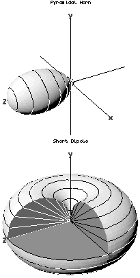
From the Rayleigh criterion, the directivity of an antenna, the angular width of the beam of radio waves it emits, is proportional to the wavelength of the radio waves divided by the width of the antenna. Small antennas around one wavelength in size, such as quarter-wave monopoles and half-wave dipoles, don't have much directivity (gain); they are omnidirectional antennas which radiate radio waves over a wide angle. To create a directional antenna (high gain antenna), which radiates radio waves in a narrow beam, two general techniques can be used:
One technique is to use reflection by large metal surfaces such as parabolic reflectors or horns, or refraction by dielectric lenses to change the direction of the radio waves, to focus the radio waves from a single low gain antenna into a beam. This type is called an aperture antenna. A parabolic dish is an example of this type of antenna.
A second technique is to use multiple antennas which are fed from the same transmitter or receiver; this is called an array antenna, or antenna array. If the currents are fed to the antennas with the proper phase, due to the phenomenon of interference the spherical waves from the individual antennas combine (superpose) in front of the array to create plane waves, a beam of radio waves traveling in a specific direction. In directions in which the waves from the individual antennas arrive in phase, the waves add together (constructive interference) to enhance the power radiated. In directions in which the individual waves arrive out of phase, with the peak of one wave coinciding with the valley of another, the waves cancel (destructive interference) reducing the power radiated in that direction. Similarly, when receiving, the oscillating currents received by the separate antennas from radio waves received from desired directions are in phase and when combined in the receiver reinforce each other, while currents from radio waves received from other directions are out of phase and when combined in the receiver cancel each other.
The radiation pattern of such an antenna consists of a strong beam in one direction, the main lobe, plus a series of weaker beams at different angles called sidelobes, usually representing residual radiation in unwanted directions. The larger the width of the antenna and the greater the number of component antenna elements, the narrower the main lobe, and the higher the gain which can be achieved, and the smaller the sidelobes will be.
Arrays in which the antenna elements are fed in phase are broadside arrays; the main lobe is emitted perpendicular to the plane of the elements.
The largest array antennas are radio interferometers used in the field of radio astronomy, in which multiple radio telescopes consisting of large parabolic antennas are linked together into an antenna array, to achieve higher resolution. Using the technique called aperture synthesis such an array can have the resolution of an antenna with a diameter equal to the distance between the antennas. In the technique called Very Long Baseline Interferometry (VLBI) dishes on separate continents have been linked, creating "array antennas" thousands of miles in size.
108MHz reflective array antenna of an SCR-270 radar used during World War II consists of 32 half-wave dipole antennas in front of a reflecting screen.
US Air Force PAVE PAWSphased array 420–450MHz radar antenna for ballistic missile detection, Alaska. The two circular arrays are each composed of 2677 crossed dipole antennas.
Some of the crossed-dipole elements in the PAVE PAWS phased array antenna, left
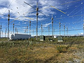
HAARP, a phased array of 180 crossed dipoles in Alaska which can transmit a 3.6MW beam of 3–10MHz radio waves into the ionosphere for research purposes
Most array antennas can be divided into two classes based on how the component antennas' axis relates to the radiation direction.
A broadside array is a one or two dimensional array in which the direction of radiation (main lobe) of the radio waves is perpendicular to the plane of the antennas. To radiate perpendicularly, the antennas must be fed in phase.
An endfire array is a linear array in which the direction of radiation is along the line of the antennas. The antennas must be fed with a phase difference equal to the separation of adjacent antennas.
There are also arrays (such as phased arrays) which don't belong to either of these categories, in which the direction of radiation is at some other angle to the antenna axis.
Array antennas can also be categorized by how the element antennas are arranged:
Driven array – This is an array in which the individual component antennas are all "driven" – connected to the transmitter or receiver. The individual antennas, which are usually identical, often consist of single driven elements, such as half-wave dipoles, but may also be composite antennas such as Yagi antennas or turnstile antennas.
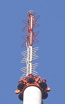
Superturnstile or Batwing array – specialized vertical antenna used for television broadcasting consisting of multiple crossed-dipole antennas mounted collinearly on a mast. High gain omnidirectional radiation pattern with wide bandwidth.
Planar array – a flat two-dimensional array of antennas. Since an array of omnidirectional antennas radiates two beams 180° apart broadside from both sides of the antenna, it is usually either mounted in front of a flat reflector, or is composed of directive antennas such as Yagi or helical antennas, to give a unidirectional beam.
Reflective array – a planar array of antennas, often half-wave dipoles fed in phase, in front of a flat reflector such as a metal plate or wire screen. This radiates a single beam of radio waves perpendicular (broadside) to the array. Used as UHF television antennas and radar antennas.
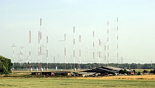
Curtain array – an outdoor wire shortwave transmitting antenna consisting of a planar array of wire dipoles suspended in front of a vertical reflector made of a "curtain" of parallel wires. Used on HF band as long distance transmitting antenna for shortwave broadcasting stations. May be steered as phased array.
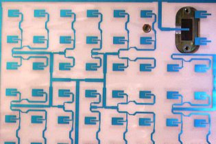
Microstrip antenna – an array of patch antennas fabricated on a printed circuit board with copper foil on the reverse side functioning as a reflector. The elements are fed through striplines made of copper foil. Used as UHF and satellite television receiving antennas.
Animation showing how a phased array works.Phased array or electronically scanned array – A planar array in which the beam can be steered electronically to point in any direction over a wide angle in front of the array, without physically moving the antenna. The current from the transmitter is fed to each component antenna through a phase shifter, controlled by a computer. By changing the relative phase of the feed currents, the beam can instantly be pointed in different directions. Widely used in military radars, this technique is rapidly spreading to civilian applications.
Passive Electronically Scanned Array (PESA) – A phased array as described above, in which the antenna elements are fed from a single transmitter or receiver through phase shifters.
Active Electronically Scanned Array (AESA) – A phased array in which each antenna element has its own transmitter and/or receiver module, controlled by a central computer. This second generation phased array technology can radiate multiple beams at multiple frequencies simultaneously, and is mostly used in sophisticated military radars.
Conformal array – a two-dimensional phased array which is not flat, but conforms to some curved surface. The individual elements are driven by phase shifters which compensate for the varying path lengths, allowing the antenna to radiate a plane wave beam. Conformal antennas are often integrated into the curving skin of aircraft and missiles, to reduce aerodynamic drag.
Smart antenna, reconfigurable antenna or adaptive array – a receiving array that estimates the direction of arrival of the radio waves and electronically optimizes the radiation pattern adaptively to receive it, synthesizing a main lobe in that direction.[3] Like a phased array it consists of multiple identical elements with phase shifters in the feed lines, controlled by a computer.
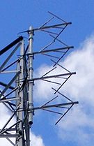
Log-periodic dipole array (LPDA) – an endfire array consisting of many dipole driven elements in a line, with gradually increasing length. It acts as a high gain broadband antenna. Used as television reception antennas and for shortwave communication.
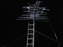
A rooftop television antenna, an endfire parasitic array consisting of a combination of a Yagi and log periodic antennaParasitic array – This is an endfire array which consist of multiple antenna elements in a line of which only one, the driven element, is connected to the transmitter or receiver, while the other elements, called parasitic elements, are not. The parasitic elements function as resonators, absorbing radio waves from the driven element and reradiating them with a different phase, to modify the radiation pattern of the antenna, increasing the power radiated in the desired direction. Since these have only one driven element they are often called "antennas" instead of "arrays".
Yagi–Uda antenna or Yagi antenna – this endfire array consists of multiple half-wave dipole elements in a line. It consists of a single driven element with multiple "director" parasitic elements in the direction of radiation, and usually a single "reflector" parasitic element behind it. They are widely used on the HF, VHF, and UHF bands as television antennas, shortwave communication antennas, and in radar arrays.
Quad antenna – This consists of multiple loop antennas in a line, with one driven loop and the others parasitic. Functions similarly to the Yagi antenna.
Periodic Arrays
Let us consider a linear array whose elements are arranged along the x-axis of an orthogonal Cartesian reference system. It is assumed that radiators have the same orientation and the same polarization of the electric field. Based on this, the array factor can be written as follows[4]
where is the number of antenna elements, is the wavenumber, and (in meters) are the complex excitation coefficient and the position of the n-th radiator, respectively, , with and being the zenith angle and azimuth angle, respectively. If the spacing between adjacent elements is constant, then it can be written that , and the array is said to be periodic. The array is periodic both spatially (physically) and in the variable . For example, if , with being the wavelength, then the magnitude of the array factor has a period, in the domain of , equal to . It is worth emphasising that is an auxiliary variable. In fact, from a physical point of view, the values of that are of interest for radiative purposes fall in the interval , which is associated with the values of and . In this case, the interval [-1,1] is called visible space. As shown further, if the definition of the variable changes, the extent of the visible space also changes accordingly.
Now, suppose that the excitation coefficients are positive real variables. In this case, always in the domain of , the array factor magnitude has a main lobe with maximum value at , called mainlobe, several secondary lobes lower than the mainlobe, called sidelobes and mainlobe replicas called grating-lobes. Grating lobes are a source of disadvantages in both transmission and reception. In fact, in transmission, they can lead to radiation in unwanted directions, while, in reception, they can be a source of ambiguity since the desired signal entering the mainlobe region could be strongly disturbed by other signals (unwanted interfering signals) entering the regions of the various grating lobes. Therefore, in periodic arrays, the spacing between adjacent radiators must not exceed a specific value to prevent the appearance of grating lobes (in the visible space)in the visible space), the spacing between adjacent radiators must not exceed a specific value. For example, as seen previously, the first grating lobes for occur in . So, in this case, there are no problems since, in this way, the grating lobes are outside the interval [-1,1].
Aperiodic Arrays
As seen above, when the spacing is constant between adjacent radiators, the array factor is characterized by the presence of grating lobes. In the literature, it has been amply demonstrated that to destroy the array factor's periodicity, the same array's geometry must also be made aperiodic.[5] It is possible to act on the positions of the radiators so that these positions are not commensurable with each other. Several methods have been developed to synthesize arrays in which also the positions represent further degrees of freedom (unknowns). There are both deterministic[6] and probabilistic[7][8] methodologies. Since the probabilistic theory of aperiodic arrays is a sufficiently systematised theory, with a strong general methodological basis, let us first concentrate on describing its peculiarities.
Suppose that the radiators positions, , are independent and identically distributed random variables whose support coincides with the whole array aperture. Consequently, the array factor is a stochastic process, whose mean is as follows[7]
Design of antenna arrays
In an antenna array providing a fixed radiation pattern, we may consider that the feed network is a part of the antenna array. Thus, the antenna array has a single port. Narrow beams can be formed, provided the phasing of each element of the array is appropriate. If, in addition, the amplitude of the excitation received by each element (during emission) is also well chosen, it is possible to synthesize a single-port array having a radiation pattern that closely approximates a specified pattern.[4] Many methods have been developed for array pattern synthesis. Additional issues to be considered are matching, radiation efficiency and bandwidth.
The design of an electronically steerable antenna array is different, because the phasing of each element can be varied, and possibly also the relative amplitude for each element. Here, the antenna array has multiple ports, so that the subject matters of matching and efficiency are more involved than in the single-port case. Moreover, matching and efficiency depend on the excitation, except when the interactions between the antennas can be ignored.
An antenna array used for spatial diversity and/or spatial multiplexing (which are different types of MIMO radio communication) always has multiple ports.[9] It is intended to receive independent excitations during emission, and to deliver more or less independent signals during reception. Here also, the subject matters of matching and efficiency are involved, especially in the case of an antenna array of a mobile device (see chapter 10 of [9]), since, in this case, the surroundings of the antenna array influence its behavior, and vary over time. Suitable matching metrics and efficiency metrics take into account the worst possible excitations.[10]
In antenna theory, a phased array usually means an electronically scanned array, a computer-controlled array of antennas which creates a beam of radio waves that can be electronically steered to point in different directions without moving the antennas. The general theory of an electromagnetic phased array also finds applications in ultrasonic and medical imaging application and in optics optical phased array.
In the field of antenna design the term radiation pattern refers to the directional (angular) dependence of the strength of the radio waves from the antenna or other source.
In telecommunications and radar, a reflective array antenna is a class of directive antennas in which multiple driven elements are mounted in front of a flat surface designed to reflect the radio waves in a desired direction. They are a type of array antenna. They are often used in the VHF and UHF frequency bands. VHF examples are generally large and resemble a highway billboard, so they are sometimes called billboard antennas. Other names are bedspring array and bowtie array depending on the type of elements making up the antenna. The curtain array is a larger version used by shortwave radio broadcasting stations.
In radio engineering, an antenna or aerial is the interface between radio waves propagating through space and electric currents moving in metal conductors, used with a transmitter or receiver. In transmission, a radio transmitter supplies an electric current to the antenna's terminals, and the antenna radiates the energy from the current as electromagnetic waves. In reception, an antenna intercepts some of the power of a radio wave in order to produce an electric current at its terminals, that is applied to a receiver to be amplified. Antennas are essential components of all radio equipment.
A parabolic antenna is an antenna that uses a parabolic reflector, a curved surface with the cross-sectional shape of a parabola, to direct the radio waves. The most common form is shaped like a dish and is popularly called a dish antenna or parabolic dish. The main advantage of a parabolic antenna is that it has high directivity. It functions similarly to a searchlight or flashlight reflector to direct radio waves in a narrow beam, or receive radio waves from one particular direction only. Parabolic antennas have some of the highest gains, meaning that they can produce the narrowest beamwidths, of any antenna type. In order to achieve narrow beamwidths, the parabolic reflector must be much larger than the wavelength of the radio waves used, so parabolic antennas are used in the high frequency part of the radio spectrum, at UHF and microwave (SHF) frequencies, at which the wavelengths are small enough that conveniently sized reflectors can be used.
Effective radiated power (ERP), synonymous with equivalent radiated power, is an IEEE standardized definition of directional radio frequency (RF) power, such as that emitted by a radio transmitter. It is the total power in watts that would have to be radiated by a half-wave dipole antenna to give the same radiation intensity as the actual source antenna at a distant receiver located in the direction of the antenna's strongest beam. ERP measures the combination of the power emitted by the transmitter and the ability of the antenna to direct that power in a given direction. It is equal to the input power to the antenna multiplied by the gain of the antenna. It is used in electronics and telecommunications, particularly in broadcasting to quantify the apparent power of a broadcasting station experienced by listeners in its reception area.
A Yagi–Uda antenna, or simply Yagi antenna, is a directional antenna consisting of two or more parallel resonant antenna elements in an end-fire array; these elements are most often metal rods acting as half-wave dipoles. Yagi–Uda antennas consist of a single driven element connected to a radio transmitter or receiver through a transmission line, and additional passive radiators with no electrical connection, usually including one so-called reflector and any number of directors. It was invented in 1926 by Shintaro Uda of Tohoku Imperial University, Japan, with a lesser role played by his boss Hidetsugu Yagi.
A directional antenna or beam antenna is an antenna which radiates or receives greater radio wave power in specific directions. Directional antennas can radiate radio waves in beams, when greater concentration of radiation in a certain direction is desired, or in receiving antennas receive radio waves from one specific direction only. This can increase the power transmitted to receivers in that direction, or reduce interference from unwanted sources. This contrasts with omnidirectional antennas such as dipole antennas which radiate radio waves over a wide angle, or receive from a wide angle.
In radio communication, an omnidirectional antenna is a class of antenna which radiates equal radio power in all directions perpendicular to an axis, with power varying with angle to the axis, declining to zero on the axis. When graphed in three dimensions (see graph) this radiation pattern is often described as doughnut-shaped. This is different from an isotropic antenna, which radiates equal power in all directions, having a spherical radiation pattern. Omnidirectional antennas oriented vertically are widely used for nondirectional antennas on the surface of the Earth because they radiate equally in all horizontal directions, while the power radiated drops off with elevation angle so little radio energy is aimed into the sky or down toward the earth and wasted. Omnidirectional antennas are widely used for radio broadcasting antennas, and in mobile devices that use radio such as cell phones, FM radios, walkie-talkies, wireless computer networks, cordless phones, GPS, as well as for base stations that communicate with mobile radios, such as police and taxi dispatchers and aircraft communications.
In radio and telecommunications a dipole antenna or doublet is the simplest and most widely used class of antenna. The dipole is any one of a class of antennas producing a radiation pattern approximating that of an elementary electric dipole with a radiating structure supporting a line current so energized that the current has only one node at each end. A dipole antenna commonly consists of two identical conductive elements such as metal wires or rods. The driving current from the transmitter is applied, or for receiving antennas the output signal to the receiver is taken, between the two halves of the antenna. Each side of the feedline to the transmitter or receiver is connected to one of the conductors. This contrasts with a monopole antenna, which consists of a single rod or conductor with one side of the feedline connected to it, and the other side connected to some type of ground. A common example of a dipole is the "rabbit ears" television antenna found on broadcast television sets.
A whip antenna is an antenna consisting of a straight flexible wire or rod. The bottom end of the whip is connected to the radio receiver or transmitter. A whip antenna is a form of monopole antenna. The antenna is designed to be flexible so that it does not break easily, and the name is derived from the whip-like motion that it exhibits when disturbed. Whip antennas for portable radios are often made of a series of interlocking telescoping metal tubes, so they can be retracted when not in use. Longer whips, made for mounting on vehicles and structures, are made of a flexible fiberglass rod around a wire core and can be up to 11 m long.
The Beverage antenna or "wave antenna" is a long-wire receiving antenna mainly used in the low frequency and medium frequency radio bands, invented by Harold H. Beverage in 1921. It is used by amateur radio, shortwave listening, and longwave radio DXers and military applications.
In antenna engineering, sidelobes are the lobes of the far field radiation pattern of an antenna or other radiation source, that are not the main lobe.
A loop antenna is a radio antenna consisting of a loop or coil of wire, tubing, or other electrical conductor, that for transmitting is usually fed by a balanced power source or for receiving feeds a balanced load. Within this physical description there are two distinct types:
A monopole antenna is a class of radio antenna consisting of a straight rod-shaped conductor, often mounted perpendicularly over some type of conductive surface, called a ground plane. The driving signal from the transmitter is applied, or for receiving antennas the output signal to the receiver is taken, between the lower end of the monopole and the ground plane. One side of the antenna feedline is attached to the lower end of the monopole, and the other side is attached to the ground plane, which is often the Earth. This contrasts with a dipole antenna which consists of two identical rod conductors, with the signal from the transmitter applied between the two halves of the antenna.
In electromagnetics, directivity is a parameter of an antenna or optical system which measures the degree to which the radiation emitted is concentrated in a single direction. It is the ratio of the radiation intensity in a given direction from the antenna to the radiation intensity averaged over all directions. Therefore, the directivity of a hypothetical isotropic radiator is 1, or 0 dBi.
A turnstile antenna, or crossed-dipole antenna, is a radio antenna consisting of a set of two identical dipole antennas mounted at right angles to each other and fed in phase quadrature; the two currents applied to the dipoles are 90° out of phase. The name reflects the notion the antenna looks like a turnstile when mounted horizontally. The antenna can be used in two possible modes. In normal mode the antenna radiates horizontally polarized radio waves perpendicular to its axis. In axial mode the antenna radiates circularly polarized radiation along its axis.
Curtain arrays are a class of large multielement directional radio transmitting wire antennas, used in the shortwave radio bands. They are a type of reflective array antenna, consisting of multiple wire dipole antennas, suspended in a vertical plane, often in front of a "curtain" reflector made of a flat vertical screen of many long parallel wires. These are suspended by support wires strung between pairs of tall steel towers, up to 90 m high. They are used for long-distance skywave transmission; they transmit a beam of radio waves at a shallow angle into the sky just above the horizon, which is reflected by the ionosphere back to Earth beyond the horizon. Curtain antennas are mostly used by international short wave radio stations to broadcast to large areas at transcontinental distances.
In radio systems, many different antenna types are used whose properties are especially crafted for particular applications. Antennas can be classified in various ways. The list below groups together antennas under common operating principles, following the way antennas are classified in many engineering textbooks.
In an antenna array made of multiple conductive elements, a driven element or active element is electrically connected to the receiver or transmitter while a parasitic element or passive radiator is not.
1 2 Sibille, Alain; Oestges, Claude; Zanella, Alberto (2011). MIMO: From Theory to Implementation. Elsevier. ISBN978-0-12-382194-2.
↑ Broydé, F.; Clavelier, E. (January 2022). "The Radiation and Transducer Efficiencies of a Multiport Antenna Array". Excem Research Papers in Electronics and Electromagnetics (4). doi:10.5281/zenodo.5816837.
This page is based on this Wikipedia article Text is available under the CC BY-SA 4.0 license; additional terms may apply. Images, videos and audio are available under their respective licenses.