
Microwave is a form of electromagnetic radiation with wavelengths shorter than other radio waves but longer than infrared waves. Its wavelength ranges from about one meter to one millimeter, corresponding to frequencies between 300 MHz and 300 GHz, broadly construed. A more common definition in radio-frequency engineering is the range between 1 and 100 GHz, or between 1 and 3000 GHz . The prefix micro- in microwave is not meant to suggest a wavelength in the micrometer range; rather, it indicates that microwaves are small, compared to the radio waves used in prior radio technology.
In electrical engineering, electrical length is a dimensionless parameter equal to the physical length of an electrical conductor such as a cable or wire, divided by the wavelength of alternating current at a given frequency traveling through the conductor. In other words, it is the length of the conductor measured in wavelengths. It can alternately be expressed as an angle, in radians or degrees, equal to the phase shift the alternating current experiences traveling through the conductor.

A log-periodic antenna (LP), also known as a log-periodic array or log-periodic aerial, is a multi-element, directional antenna designed to operate over a wide band of frequencies. It was invented by John Dunlavy in 1952.

In radio engineering, an antenna or aerial is an electronic device that converts an alternating electric current into radio waves (transmitting), or radio waves into an electric current (receiving). It is the interface between radio waves propagating through space and electric currents moving in metal conductors, used with a transmitter or receiver. In transmission, a radio transmitter supplies an electric current to the antenna's terminals, and the antenna radiates the energy from the current as electromagnetic waves. In reception, an antenna intercepts some of the power of a radio wave in order to produce an electric current at its terminals, that is applied to a receiver to be amplified. Antennas are essential components of all radio equipment.
Super high frequency (SHF) is the ITU designation for radio frequencies (RF) in the range between 3 and 30 gigahertz (GHz). This band of frequencies is also known as the centimetre band or centimetre wave as the wavelengths range from one to ten centimetres. These frequencies fall within the microwave band, so radio waves with these frequencies are called microwaves. The small wavelength of microwaves allows them to be directed in narrow beams by aperture antennas such as parabolic dishes and horn antennas, so they are used for point-to-point communication and data links and for radar. This frequency range is used for most radar transmitters, wireless LANs, satellite communication, microwave radio relay links, satellite phones, and numerous short range terrestrial data links. They are also used for heating in industrial microwave heating, medical diathermy, microwave hyperthermy to treat cancer, and to cook food in microwave ovens.
A resonator is a device or system that exhibits resonance or resonant behavior. That is, it naturally oscillates with greater amplitude at some frequencies, called resonant frequencies, than at other frequencies. The oscillations in a resonator can be either electromagnetic or mechanical. Resonators are used to either generate waves of specific frequencies or to select specific frequencies from a signal. Musical instruments use acoustic resonators that produce sound waves of specific tones. Another example is quartz crystals used in electronic devices such as radio transmitters and quartz watches to produce oscillations of very precise frequency.
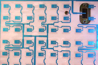
In telecommunication, a microstrip antenna usually is an antenna fabricated using photolithographic techniques on a printed circuit board (PCB). It is a kind of internal antenna. They are mostly used at microwave frequencies. An individual microstrip antenna consists of a patch of metal foil of various shapes on the surface of a PCB, with a metal foil ground plane on the other side of the board. Most microstrip antennas consist of multiple patches in a two-dimensional array. The antenna is usually connected to the transmitter or receiver through foil microstrip transmission lines. The radio frequency current is applied between the antenna and ground plane. Microstrip antennas have become very popular in recent decades due to their thin planar profile which can be incorporated into the surfaces of consumer products, aircraft and missiles; their ease of fabrication using printed circuit techniques; the ease of integrating the antenna on the same board with the rest of the circuit, and the possibility of adding active devices such as microwave integrated circuits to the antenna itself to make active antennas Patch antenna. Based on its origin, microstrip consists of two words, namely micro and is defined as a type of antenna that has a blade/piece shape and is very thin/small.

In radio-frequency engineering and communications engineering, a waveguide is a hollow metal pipe used to carry radio waves. This type of waveguide is used as a transmission line mostly at microwave frequencies, for such purposes as connecting microwave transmitters and receivers to their antennas, in equipment such as microwave ovens, radar sets, satellite communications, and microwave radio links.
The spurline is a type of radio-frequency and microwave distributed element filter with band-stop (notch) characteristics, most commonly used with microstrip transmission lines. Spurlines usually exhibit moderate to narrow-band rejection, at about 10% around the central frequency.

A Vivaldi antenna or Vivaldi aerial or tapered slot antenna is a co-planar broadband-antenna, which can be made from a solid piece of sheet metal, a printed circuit board, or from a dielectric plate metalized on one or both sides.
A distributed-element filter is an electronic filter in which capacitance, inductance, and resistance are not localised in discrete capacitors, inductors, and resistors as they are in conventional filters. Its purpose is to allow a range of signal frequencies to pass, but to block others. Conventional filters are constructed from inductors and capacitors, and the circuits so built are described by the lumped element model, which considers each element to be "lumped together" at one place. That model is conceptually simple, but it becomes increasingly unreliable as the frequency of the signal increases, or equivalently as the wavelength decreases. The distributed-element model applies at all frequencies, and is used in transmission-line theory; many distributed-element components are made of short lengths of transmission line. In the distributed view of circuits, the elements are distributed along the length of conductors and are inextricably mixed together. The filter design is usually concerned only with inductance and capacitance, but because of this mixing of elements they cannot be treated as separate "lumped" capacitors and inductors. There is no precise frequency above which distributed element filters must be used but they are especially associated with the microwave band.

Metamaterial antennas are a class of antennas which use metamaterials to increase performance of miniaturized antenna systems. Their purpose, as with any electromagnetic antenna, is to launch energy into free space. However, this class of antenna incorporates metamaterials, which are materials engineered with novel, often microscopic, structures to produce unusual physical properties. Antenna designs incorporating metamaterials can step-up the antenna's radiated power.

A tunable metamaterial is a metamaterial with a variable response to an incident electromagnetic wave. This includes remotely controlling how an incident electromagnetic wave interacts with a metamaterial. This translates into the capability to determine whether the EM wave is transmitted, reflected, or absorbed. In general, the lattice structure of the tunable metamaterial is adjustable in real time, making it possible to reconfigure a metamaterial device during operation. It encompasses developments beyond the bandwidth limitations in left-handed materials by constructing various types of metamaterials. The ongoing research in this domain includes electromagnetic band gap metamaterials (EBG), also known as photonic band gap (PBG), and negative refractive index material (NIM).

A waveguide filter is an electronic filter constructed with waveguide technology. Waveguides are hollow metal conduits inside which an electromagnetic wave may be transmitted. Filters are devices used to allow signals at some frequencies to pass, while others are rejected. Filters are a basic component of electronic engineering designs and have numerous applications. These include selection of signals and limitation of noise. Waveguide filters are most useful in the microwave band of frequencies, where they are a convenient size and have low loss. Examples of microwave filter use are found in satellite communications, telephone networks, and television broadcasting.

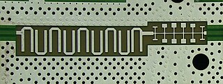
A substrate-integrated waveguide (SIW) is a synthetic rectangular electromagnetic waveguide formed in a dielectric substrate by densely arraying metallized posts or via holes that connect the upper and lower metal plates of the substrate. The waveguide can be easily fabricated with low-cost mass-production using through-hole techniques, where the post walls consists of via fences. SIW is known to have similar guided wave and mode characteristics to conventional rectangular waveguide with equivalent guide wavelength.
A via fence, also called a picket fence, is a structure used in planar electronic circuit technologies to improve isolation between components which would otherwise be coupled by electromagnetic fields. It consists of a row of via holes which, if spaced close enough together, form a barrier to electromagnetic wave propagation of slab modes in the substrate. Additionally if radiation in the air above the board is also to be suppressed, then a strip pad with via fence allows a shielding can to be electrically attached to the top side, but electrically behave as if it continued through the PCB.
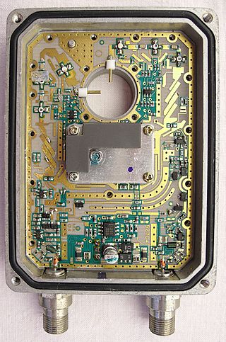
Planar transmission lines are transmission lines with conductors, or in some cases dielectric (insulating) strips, that are flat, ribbon-shaped lines. They are used to interconnect components on printed circuits and integrated circuits working at microwave frequencies because the planar type fits in well with the manufacturing methods for these components. Transmission lines are more than simply interconnections. With simple interconnections, the propagation of the electromagnetic wave along the wire is fast enough to be considered instantaneous, and the voltages at each end of the wire can be considered identical. If the wire is longer than a large fraction of a wavelength, these assumptions are no longer true and transmission line theory must be used instead. With transmission lines, the geometry of the line is precisely controlled so that its electrical behaviour is highly predictable. At lower frequencies, these considerations are only necessary for the cables connecting different pieces of equipment, but at microwave frequencies the distance at which transmission line theory becomes necessary is measured in millimetres. Hence, transmission lines are needed within circuits.

An inverted-F antenna is a type of antenna used in wireless communication, mainly at UHF and microwave frequencies. It consists of a monopole antenna running parallel to a ground plane and grounded at one end. The antenna is fed from an intermediate point a distance from the grounded end. The design has two advantages over a simple monopole: the antenna is shorter and more compact, allowing it to be contained within the case of the mobile device, and it can be impedance matched to the feed circuit by the designer, allowing it to radiate power efficiently, without the need for extraneous matching components.
In radio systems, many different antenna types are used whose properties are especially crafted for particular applications.
A defected ground structure (DGS) is a purposefully created defect on the ground plane of a printed microstrip board. It is typically created in the form of an etched-out pattern on the ground plane. DGS is a simplified form of Electromagnetic Band Gap (EBG) structure. This EBG is a periodic pattern featuring a band-stop property in microstrip transmission line and circuit applications, but the DGS comprises a single defect or a very limited number of defects with periodic/aperiodic configurations.

