An umbrella antenna is a capacitively top-loaded wire monopole antenna, consisting in most cases of a mast fed at the ground end, to which a number of radial wires are connected at the top, sloping downwards.[1] One side of the feedline supplying power from the transmitter is connected to the mast, and the other side to a ground (earthing) system of radial wires buried in the earth under the antenna. They are used as transmitting antennas below 1MHz, in the MF, LF and particularly the VLF bands, at frequencies sufficiently low that it is impractical or infeasible to build a full size quarter-wave monopole antenna. The outer end of each radial wire, sloping down from the top of the antenna, is connected by an insulator to a supporting rope or cable anchored to the ground; the radial wires can also support the mast as guy wires. The radial wires make the antenna look like the wire frame of a giant umbrella (without the cloth) hence the name.
Diagram of base-fed umbrella antenna. The red cylinders are insulators. Buried under the antenna is a radial wire ground system (not shown).
Design
The antenna is supported by a central steel tubular or lattice mast. The top of the mast is attached to a ring of equally spaced radial wires extending diagonally to near the ground, where each is attached with a strain insulator to a length of non-radiating wire or rope which is anchored to the ground. The umbrella wires may also serve structurally as guy lines to support the mast. There are several different methods of feeding power from the transmitter to the antenna:
In base feed, the mast is supported on a thick ceramic insulator which keeps it insulated from the ground, and the feedline from the transmitter is attached to the base of the mast. The conductive steel mast serves as the monopole radiator. Alternately, in high power antennas, the mast is grounded, the umbrella wires are insulated where they connect to the central mast, and are attached to vertical radiator wires that hang down parallel to the mast which are fed at the bottom. This construction is used in high power antennas in which the very high voltage on the antenna would make it difficult to insulate the mast from the ground.[2][3][4]
Under the antenna is a large ground (Earthing) system connected to the opposite side of the feedline, consisting of wires buried in the Earth extending radially from a terminal at the base of the mast out to the edge of the umbrella wires.
Top of 432m mast of stationG Omega antenna, Victoria, Australia, showing insulators attaching the 16umbrella wires to the mast
Alternatively, in radial feed, the antenna can be fed power by applying the transmitter current to the ends of one or more of the radial wires instead of the mast. In this case the central mast is grounded. As with wire feeders, this avoids the need for a mast support insulator, and also does not require an isolator in the power cables for the mast's aircraft warning lights. This construction was used in three large umbrella antennas for the obsolete Omega navigation system which operated at 10–14kHz, to eliminate the very difficult problem of insulating the mast base against the 200kV antenna potential.
Since the antenna is shorter than the resonant length of one-quarter wavelength, it has capacitance. In order to cancel the capacitive reactance and make it resonant so it can be fed power efficiently, an impedance matching inductor called a loading coil is connected in series with the feedline at the base of the antenna.
Operation
The vertical mast, isolated from the ground, or the vertical radiator wires, functions as a resonantmonopole antenna.[2][3][4] At the low frequencies used, the height of the mast is much less than its resonant length, one quarter wavelength(), so it makes a very electrically short antenna; it has very low radiation resistance and without the topload wires would be a very inefficient radiator. The oscillating current from the transmitter travels up the mast and divides approximately equally among the topload wires. It is reflected from the ends of the wires and travels back down the mast. The outgoing and reflected current superpose, forming a standing wave consisting of the tail part of a sine wave.
Due to ground reflections and the symmetrical placement of the topload wires, measured far from the antenna the radio waves radiated from the umbrella-like spoke wires largely cancel each other out, so the spoke wires themselves radiate almost no radio power. Instead the umbrella-wires function as a capacitive top load replacing some or all of the capacitance that would be provided by the top of a full-length quarter-wave mast. The ground wires buried or laid on the earth under the antenna function as the corresponding bottom plate of the giant 'capacitor'. The added capacitance increases the current in the vertical mast due to the extra charge required to charge and discharge the top load each half of the RF cycle. In the best case, this can double the total current, and quadruple the radiated power, increasing the signal up to 6dB from the level it would be with no top loading.
To tune out the large capacitive reactance of the antenna and make it resonant at the operating frequency so it can be fed power efficiently, a large inductor (loading coil) is placed in the feedline in series with the antenna, at its base. The other side of the feedline from the transmitter is connected to the ground system. The antenna and coil form a tuned circuit. Their large reactance and low resistance usually give the antenna a high Q factor, so it has a narrow bandwidth over which it can work. In large umbrella antennas used in the very low frequency band, the bandwidth of the antenna can be less than 100hertz.
Below are several grounded mast umbrella antenna variations developed by the US military in the 1970s for use on the low frequency band.
Pan polar antenna
Nord antenna
Radiation pattern
The umbrella antenna radiates vertically polarised radio waves in an omnidirectionalradiation pattern, with equal power emitted in all horizontal directions, with maximum signal strength radiated in horizontal directions, falling monotonically with elevation angle to zero at the zenith. Due to the large top load they are usually more efficient than the other common top loaded antennas, the “flattop” or ‘T’ antenna, at low frequencies, and are widely used in the VLF band.
Ground waves are vertically polarized waves which travel away from the antenna horizontally just above the ground. Umbrella antennas are good ground wave antennas, and are used as radio broadcasting antennas in the MF and LF bands.
The gain of an umbrella antenna over perfectly conducting ground, like other electrically short monopole antennas, is approximately 3.52dBi if it is significantly shorter than
Since the diagonal wires are sloped down, the current in them has a vertical component.[3] This current is in a direction opposite to the current in the mast, so far from the mast the radio waves radiated by it are 180° out of phase with the radio waves from the mast, and partially cancel them. Thus the umbrella wires partially shield the mast, reducing the power radiated. With enough umbrella wires all the radio waves emitted by the portion of mast above the bottom of the umbrella is blocked, and the only radiation is from the portion of the mast below the umbrella.
Applications
Due to their large capacitive topload, umbrella antennas are some of the most efficient antenna designs at low frequencies, and are used for transmitters in the LF and VLF bands for navigational aids and military communication. They are in common use for commercial medium-wave and longwaveAM broadcasting stations. Umbrella antennas with heights of 15–460metres are in service.[citation needed] The largest umbrella antennas are the trideco antennas (below) built for VLF naval transmitting stations which communicate with submerged submarines.
Eight umbrella antennas 350metres high are in use in an array at the German VLF transmitter DHO38, operating at about 20kHz with high radiation efficiency even though they are less than 1/ 40 wavelength high.[citation needed]
With the progressing world-wide adoption of two new amateur radio bands at 630metres and 2200metres, amateurs with adequate real estate have resumed use of this design.
Some of the antenna masts. The structures at the base of the masts are huge counterweights which tension the topload wires.
Cutler VLF antenna array layout
The trideco antenna array at the US Navy's Cutler VLF transmitter at Cutler, Maine, which transmits tactical orders to submerged submarines at a frequency of 24kHz and a power of 1.8megawatts, one of the most powerful transmitters in the world. It consists of two identical trideco antennas, each consisting of 13towers supporting a 6pointed wire topload about a mile across.
Central mast and 6vertical radiator feeders connection to the horizontal topload wires, showing the long 50ftinsulator strings and corona rings required to withstand the 200kV voltage on the antenna.
Feeders surrounding the central mast
The complete antenna
The seven-mast trideco antenna at Anthorn Radio Station on the coast of Cumbria, England, that transmits VLF signals to British Navy submarines and those of other NATO countries.
The trideco antenna is a huge specialized umbrella antenna used in a few high power military transmitters at very low frequency (VLF).[5][6] In a conventional umbrella antenna, the use of the sloping guy wires as the capacitive top load has some disadvantages: First, since the umbrella wires must be anchored to the ground, their length is limited. At low frequencies the length of topload wires required is far longer than can be used for guy wires, without additional supporting masts the wires would sag to the ground. Second, since the wires are sloping, the current in them has a vertical component. This vertical current is in the opposite direction to the current in the mast, so the radio waves radiated by it are 180° out of phase with the mast radiation, and partially cancels it.
In the trideco design the top load wires extend horizontally from the top of the central mast, supported by a ring of 12masts surrounding the central mast, to create a radial wire "capacitor plate" parallel with the Earth, driven at the center.[7][8] The topload wires are in the form of six rhomboidal (diamond-shaped) panels extending symmetrically from the central mast at angles of 60°, giving the antenna the form of a six-pointed star when seen from above. Instead of using the central mast itself as a radiator, each panel is connected to a vertical radiator wire next to the central mast, and the six radiator wires are fed in phase at the base. This eliminates the difficult problem of insulating the mast from the ground at the extremely high voltages used. It also allows the possibility of shutting down power to one of the panels, and lowering it to the ground for maintenance while the rest of the antenna is operating. Buried in the ground under the antenna is an enormous radial ground system, which forms the bottom 'plate' of the capacitor with the overhead top load. The antenna must be very large at the VLF frequencies used; the supporting masts are 250–300 metres (820–980ft) high, and the topload is about 1,900 metres (6,200ft) in diameter.
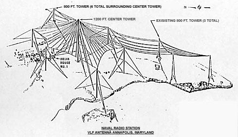
The trideco antenna was developed for high power naval transmitters, which transmit on frequencies between 15 and 30kHz at powers up to 2megawatts, to communicate with submerged submarines worldwide. It is the most efficient antenna design found so far for this frequency range, achieving efficiencies of 70-80% where other VLF antenna designs have efficiency of 15-30% due to the low radiation resistance of the very electrically short monopole.[8] The antenna was invented by Boynton Hagaman of Development Engineering Co. (DECO) and first installed at Cutler, Maine in 1961.[9] The inspiration for the design was the umbrella antenna of the 1 megawatt Goliath transmitter built by Nazi Germany's navy in 1943 at Kalbe, Saxony-Anhalt, Germany. Today trideco antennas are located at a few military bases around the world, such as Cutler naval radio station in Maine, U.S.; Harold E. Holt Naval Communication Station, Exmouth, Australia; and Anthorn Radio Station, Anthorn, UK. A modified 3panel antenna was located at NSS Annapolis, Annapolis, Maryland, but was decommissioned in 1990.
History
Fessenden's 1905 Brant Rock, Mass, 400 ft umbrella antenna
100 meter umbrella antenna of spark-gap transmitter at Nauen Transmitter Station, Nauen, Germany, 1906.
220ft umbrella antenna of 200kHz wireless telegraphy station near Newcastle, England, 1910.
Larger 200m umbrella antenna built at Nauen in 1911
Umbrella antennas were invented during the wireless telegraphy era, about 1900 to 1920, and used with spark-gap transmitters on longwave bands to transmit information by Morse code. Low frequencies were used for long distance transcontinental communication, and antennas were electrically short, so capacitively toploaded antennas were used. Umbrella antennas developed from large multi-wire capacitive antennas used by Guglielmo Marconi during his efforts to achieve reliable transatlantic communication.
One of the first antennas that used this design was the tubular 420 foot (130m) mast erected in 1905 by Reginald Fessenden for his experimental spark gap transmitter at Brant Rock, Massachusetts with which he made the first two-way transatlantic transmission, communicating with an identical antenna in Machrihanish, Scotland.[10] The wires attached to the top (either 4 or 8, depending on source) were electrically connected to the mast and stretched diagonally down to the surface, where they were insulated from the ground. Another early example is the umbrella antenna built in 1906 by Adolf Slaby at Nauen Transmitter Station, Germany's first long range radio station, consisting of a 100-metre (330ft) steel lattice tower radiator with 162umbrella cables attached to the top, anchored by hemp ropes to the ground 200m from the tower. Small umbrella antennas were widely used with portable transmitters by military signal corps during World War I, since there was no possibility of setting up full-sized quarter-wave antennas.
Umbrella antennas were used at most OMEGA Navigation System transmitters, operating around 10kHz, at Decca Navigator stations and at LORAN-C stations, operating at 100kHz with central masts approximately 200metres tall, before those systems were shut down.
↑Hagaman, Boynton (April 2000). Designing the Giant Antennas. April 2000 AMRAD Meeting. Amateur Radio Research and Development Corporation (AMRAD). Retrieved 9 June 2020. Synopsis of a presentation.
This page is based on this Wikipedia article Text is available under the CC BY-SA 4.0 license; additional terms may apply. Images, videos and audio are available under their respective licenses.


