This article needs additional citations for verification .(November 2011) |
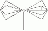
In radio systems, a biconical antenna is a broad-bandwidth antenna made of two roughly conical conductive objects, nearly touching at their points. [1]
Biconical antennas are broadband dipole antennas, typically exhibiting a bandwidth of three octaves or more. A common subtype is the bowtie antenna, essentially a flattened version of the biconical design which is often used for short-range UHF television reception. These are also sometimes referred to as butterfly antennas. [2]
The biconical antenna has a broad bandwidth because it is an example of a traveling wave structure; the analysis for a theoretical infinite antenna resembles that of a transmission line. For an infinite antenna, the characteristic impedance at the point of connection is a function of the cone angle only and is independent of the frequency.
Practical antennas have finite length and a definite resonant frequency. [1] A simple conical monopole antenna is a wire approximation of the solid biconical antenna and has increased bandwidth (over a simple monopole).
Biconical (or "bicon") antennas are often used in electromagnetic interference (EMI) testing either for immunity testing, or emissions testing.
While the bicon is very broadband, it exhibits poor transmitting efficiency at frequencies at the low end of its range, resulting in low field strengths when compared to the input power. Log periodic dipole arrays, Yagi–Uda antennas, and reverberation chambers have shown to achieve much higher field strengths for the power input than a simple biconical antenna in an anechoic chamber.
However, when the goal is to fully characterize a modulated or impulse signal, rather than merely measuring peak and average spectrum energy content, a reverberation chamber is a poor choice for a test environment.
Electromagnetic compatibility (EMC) is the ability of electrical equipment and systems to function acceptably in their electromagnetic environment, by limiting the unintentional generation, propagation and reception of electromagnetic energy which may cause unwanted effects such as electromagnetic interference (EMI) or even physical damage to operational equipment. The goal of EMC is the correct operation of different equipment in a common electromagnetic environment. It is also the name given to the associated branch of electrical engineering.
In electrical engineering, a ground plane is an electrically conductive surface, usually connected to electrical ground.
A log-periodic antenna (LP), also known as a log-periodic array or log-periodic aerial, is a multi-element, directional antenna designed to operate over a wide band of frequencies. It was invented by John Dunlavy in 1952.
In telecommunication, especially radio communication, spread spectrum are techniques by which a signal generated with a particular bandwidth is deliberately spread in the frequency domain over a wider frequency band. Spread-spectrum techniques are used for the establishment of secure communications, increasing resistance to natural interference, noise, and jamming, to prevent detection, to limit power flux density, and to enable multiple-access communications.
A fractal antenna is an antenna that uses a fractal, self-similar design to maximize the effective length, or increase the perimeter, of material that can receive or transmit electromagnetic radiation within a given total surface area or volume.
In electronics and telecommunications, a radio transmitter or just transmitter is an electronic device which produces radio waves with an antenna with the purpose of signal transmission up to a radio receiver. The transmitter itself generates a radio frequency alternating current, which is applied to the antenna. When excited by this alternating current, the antenna radiates radio waves.
Ultra high frequency (UHF) is the ITU designation for radio frequencies in the range between 300 megahertz (MHz) and 3 gigahertz (GHz), also known as the decimetre band as the wavelengths range from one meter to one tenth of a meter. Radio waves with frequencies above the UHF band fall into the super-high frequency (SHF) or microwave frequency range. Lower frequency signals fall into the VHF or lower bands. UHF radio waves propagate mainly by line of sight; they are blocked by hills and large buildings although the transmission through building walls is strong enough for indoor reception. They are used for television broadcasting, cell phones, satellite communication including GPS, personal radio services including Wi-Fi and Bluetooth, walkie-talkies, cordless phones, satellite phones, and numerous other applications.
In radio engineering, an antenna or aerial is the interface between radio waves propagating through space and electric currents moving in metal conductors, used with a transmitter or receiver. In transmission, a radio transmitter supplies an electric current to the antenna's terminals, and the antenna radiates the energy from the current as electromagnetic waves. In reception, an antenna intercepts some of the power of a radio wave in order to produce an electric current at its terminals, that is applied to a receiver to be amplified. Antennas are essential components of all radio equipment.
This is an index of articles relating to electronics and electricity or natural electricity and things that run on electricity and things that use or conduct electricity.
Radiation resistance is that part of an antenna's feedpoint electrical resistance caused by the emission of radio waves from the antenna. A radio transmitter excites with a radio frequency alternating current an antenna, which radiates the exciting energy as radio waves. Because the antenna is absorbing the energy it is radiating from the transmitter, the antenna's input terminals present a resistance to the current from the transmitter.
A whip antenna is an antenna consisting of a straight flexible wire or rod. The bottom end of the whip is connected to the radio receiver or transmitter. A whip antenna is a form of monopole antenna. The antenna is designed to be flexible so that it does not break easily, and the name is derived from the whip-like motion that it exhibits when disturbed. Whip antennas for portable radios are often made of a series of interlocking telescoping metal tubes, so they can be retracted when not in use. Longer whips, made for mounting on vehicles and structures, are made of a flexible fiberglass rod around a wire core and can be up to 11 m long.
A horn antenna or microwave horn is an antenna that consists of a flaring metal waveguide shaped like a horn to direct radio waves in a beam. Horns are widely used as antennas at UHF and microwave frequencies, above 300 MHz. They are used as feed antennas for larger antenna structures such as parabolic antennas, as standard calibration antennas to measure the gain of other antennas, and as directive antennas for such devices as radar guns, automatic door openers, and microwave radiometers. Their advantages are moderate directivity, broad bandwidth, low losses, and simple construction and adjustment.
A discone antenna is a version of a biconical antenna in which one of the cones is replaced by a disc. It is usually mounted vertically, with the disc at the top and the cone beneath.
A television antenna is an antenna specifically designed for use with a television receiver (TV) to receive over-the-air broadcast television signals from a television station. Television reception is dependent upon the antenna as well as the transmitter. Terrestrial television is broadcast on frequencies from about 47 to 250 MHz in the very high frequency (VHF) band, and 470 to 960 MHz in the ultra high frequency (UHF) band in different countries. Television antennas are manufactured in two different types: "indoor" antennas, to be located on top of or next to the television set, and "outdoor" antennas, mounted on a mast on top of the owner's house. They can also be mounted in a loft or attic, where the dry conditions and increased elevation are advantageous for reception and antenna longevity. Outdoor antennas are more expensive and difficult to install but are necessary for adequate reception in fringe areas far from television stations. The most common types of indoor antennas are the dipole and loop antennas, and for outdoor antennas the Yagi, log periodic, and for UHF channels the multi-bay reflective array antenna.
A monopole antenna is a class of radio antenna consisting of a straight rod-shaped conductor, often mounted perpendicularly over some type of conductive surface, called a ground plane. The driving signal from the transmitter is applied, or for receiving antennas the output signal to the receiver is taken, between the lower end of the monopole and the ground plane. One side of the antenna feedline is attached to the lower end of the monopole, and the other side is attached to the ground plane, which is often the Earth. This contrasts with a dipole antenna which consists of two identical rod conductors, with the signal from the transmitter applied between the two halves of the antenna.
A corner reflector antenna is a type of directional antenna used at VHF and UHF frequencies. It was invented by John D. Kraus in 1938. It consists of a dipole driven element mounted in front of two flat rectangular reflecting screens joined at an angle, usually 90°. Corner reflector antennas have moderate gain of 10–15 dB, high front-to-back ratio of 20–30 dB, and wide bandwidth.
A reference antenna is an antenna with known performance. It is normally used to calibrate other systems.
A shortwave broadband antenna is a radio antenna that can be used for transmission of any shortwave radio band from among the greater part of the shortwave radio spectrum, without requiring any band-by-band adjustment of the antenna. Generally speaking, there is no difficulty in building an adequate receiving antenna; the challenge is designing an antenna which can be used for transmission without an adjustable impedance matching network.
In radio systems, many different antenna types are used whose properties are especially crafted for particular applications. Most often, the greatest effect is due to the size (wavelength) of the radio waves the antenna is to intercept or produce; one competing second effect is differences in optimization for receiving and for transmitting; another competing influence is the number and bandwidth of the frequenc(y/ies) that any single antenna must intercept or emit.