Beverage antenna

Last updated
The AT&T receiving Beverage antenna (left) and radio receiver (right) at Houlton, Maine, used for transatlantic telephone calls, from a 1920s magazine Bell telephone magazine (1922) (14569732060).jpg
The AT&T receiving Beverage antenna (left) and radio receiver (right) at Houlton, Maine, used for transatlantic telephone calls, from a 1920s magazine

The Beverage antenna or "wave antenna" is a long-wire receiving antenna mainly used in the low frequency and medium frequency radio bands, invented by Harold H. Beverage in 1921. [1] It is used by amateur radio operators, shortwave listeners, longwave radio DXers and for military applications.

Contents

A Beverage antenna consists of a horizontal wire from one-half to several wavelengths long (tens to hundreds of meters; yards at HF to several kilometres; miles for longwave) suspended above the ground, with the feedline to the receiver attached to one end, and the other end of the wire terminated through a resistor to ground. [2] [3] The antenna has a unidirectional radiation pattern with the main lobe of the pattern at a shallow angle into the sky off the resistor-terminated end, making it ideal for reception of long distance skywave (skip) transmissions from stations over the horizon which reflect off the ionosphere. However the antenna must be built so the wire points in the direction of the transmitter(s) to be received.

The advantages of the Beverage are excellent directivity, a wider bandwidth than resonant antennas, and a strong ability to receive distant and overseas transmitters. Its disadvantages are its physical size, requiring considerable land area, and inability to rotate to change the direction of reception. Installations often use multiple Beverage antennas to provide wide azimuth coverage.

History

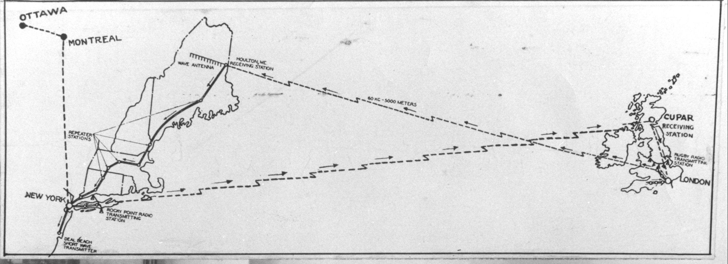
Harold Beverage experimented with receiving antennas similar to the Beverage antenna in 1919 at the Otter Cliffs Radio Station. [4] [5] He discovered in 1920 that an otherwise nearly bidirectional long-wire antenna becomes unidirectional by placing it close to the lossy earth and by terminating one end of the wire with a resistor. In 1921, Beverage was granted a patent for his antenna. That year, Beverage long-wave receiving antennas up to 14 km (9 miles) long had been installed at RCA's Riverhead, New York, [6] Belfast, Maine, [7] Belmar, New Jersey, [8] and Chatham, Massachusetts [9] receiver stations for transatlantic radiotelegraphy traffic. Perhaps the largest Beverage antenna—an array of four phased Beverages [10] 5 km (3 miles) long and 3 km (2 miles) wide—was built by AT&T in Houlton, Maine, for the first transatlantic telephone system [11] opened in 1927.

Description

Animation showing how the antenna works. Due to ground resistance the electric field of the radio wave (E, big red arrows) is at an angle th to the vertical, creating a horizontal component parallel to the antenna wire (small red arrows). The horizontal electric field creates a traveling wave of oscillating current (I, blue line) and voltage along the wire, which increases in amplitude with distance from the end. When it reaches the driven end (left), the current passes through the transmission line to the receiver. Radio waves in the other direction, toward the terminated end, create traveling waves which are absorbed by the terminating resistor R, so the antenna has a unidirectional pattern. Beverage antenna animation 408x212x15ms.gif
Animation showing how the antenna works. Due to ground resistance the electric field of the radio wave (E, big red arrows) is at an angle θ to the vertical, creating a horizontal component parallel to the antenna wire (small red arrows). The horizontal electric field creates a traveling wave of oscillating current (I, blue line) and voltage along the wire, which increases in amplitude with distance from the end. When it reaches the driven end (left), the current passes through the transmission line to the receiver. Radio waves in the other direction, toward the terminated end, create traveling waves which are absorbed by the terminating resistor R, so the antenna has a unidirectional pattern.
A Beverage antenna that can be improvised for military field communications, from a 1995 U.S. Army field manual. Rather than being grounded, the resistor is attached to a second lower wire which serves as a counterpoise, an artificial ground for the transmitter. The antenna's main lobe, its direction of greatest sensitivity, is to the right, off the end of the wire that is terminated in the resistor. Figure D-11 Long-wire antenna (FM 7-93 1995).gif
A Beverage antenna that can be improvised for military field communications, from a 1995 U.S. Army field manual. Rather than being grounded, the resistor is attached to a second lower wire which serves as a counterpoise, an artificial ground for the transmitter. The antenna's main lobe, its direction of greatest sensitivity, is to the right, off the end of the wire that is terminated in the resistor.

The Beverage antenna consists of a horizontal wire one-half to several wavelengths long, suspended close to the ground, usually 3 to 6 m (10 to 20 feet) high, pointed in the direction of the signal source. [3] [2] At the end toward the signal source it is terminated by a resistor to ground approximately equal in value to the characteristic impedance of the antenna considered as a transmission line, usually 400 to 800 ohms. At the other end it is connected to the receiver with a transmission line, through a balun to match the line to the antenna's characteristic impedance.

Operation

Unlike other wire antennas such as dipole or monopole antennas which act as resonators, with the radio currents traveling in both directions along the element, bouncing back and forth between the ends as standing waves, the Beverage antenna is a traveling wave antenna; the radio frequency current travels in one direction along the wire, in the same direction as the radio waves. [3] [2] [12] The lack of resonance gives it a wider bandwidth than resonant antennas. It receives vertically polarized radio waves, but unlike other vertically polarized antennas it is suspended close to the ground, and requires some resistance in the ground to work.

The Beverage antenna relies on "wave tilt" for its operation. [13] At low and medium frequencies, a vertically polarized radio frequency electromagnetic wave traveling close to the surface of the earth with finite ground conductivity sustains a loss that causes the wavefront to "tilt over" at an angle. [3] [2] [12] The electric field is not perpendicular to the ground but at an angle, producing an electric field component parallel to the Earth's surface. If a horizontal wire is suspended close to the Earth and approximately parallel to the wave's direction, the electric field generates an oscillating RF current wave traveling along the wire, propagating in the same direction as the wavefront. The RF currents traveling along the wire add in phase and amplitude throughout the length of the wire, producing maximum signal strength at the far end of the antenna where the receiver is connected.

The antenna wire and the ground under it together can be thought of as a "leaky" transmission line which absorbs energy from the radio waves. [12] The velocity of the current waves in the antenna is less than the speed of light due to the ground. The velocity of the wavefront along the wire is also less than the speed of light due to its angle. At a certain angle θmax the two velocities are equal. At this angle the gain of the antenna is maximum, so the radiation pattern has a main lobe at this angle. The angle of the main lobe is [14]

where

is the length of the antenna wire,
is the wavelength.

The antenna has a unidirectional reception pattern, because RF signals arriving from the other direction, from the receiver end of the wire, induce currents propagating toward the terminated end, where they are absorbed by the terminating resistor.

Gain

While Beverage antennas have excellent directivity, because they are close to lossy Earth, they do not produce absolute gain; their gain is typically from −20 to −10 dBi. This is rarely a problem, because the antenna is used at frequencies where there are high levels of atmospheric radio noise. At these frequencies the atmospheric noise, and not receiver noise, determines the signal-to-noise ratio, so an inefficient antenna can be used. The weak signal from the antenna can be amplified in the receiver without introducing significant noise. The antenna is not used as a transmitting antenna since, to do so, would mean a large portion of the drive power is wasted in the terminating resistor [15]

Directivity increases with the length of the antenna. While directivity begins to develop at a length of only 0.25 wavelength, directivity becomes more significant at one wavelength and improves steadily until the antenna reaches a length of about two wavelengths. In Beverages longer than two wavelengths, directivity does not increase because the currents in the antenna cannot remain in phase with the radio wave.

Implementation

A single-wire Beverage antenna is typically a single straight copper wire, between one-half and two wavelengths long, run parallel to the Earth's surface in the direction of the desired signal. The wire is suspended by insulated supports above the ground. [16] A non-inductive resistor approximately equal to the characteristic impedance of the wire, about 400 to 600 ohms, is connected from the far end of the wire to a ground rod. The other end of the wire is connected to the feedline to the receiver. [17]

A dual-wire variant is sometimes utilized for rearward null steering or for bidirectional switching. The antenna can also be implemented as an array of 2 to 128 or more elements in broadside, endfire, and staggered configurations, offering significantly improved directivity otherwise very difficult to attain at these frequencies. A four-element broadside/staggered Beverage array was used by AT&T at their longwave telephone receiver site in Houlton, Maine. Very large phased Beverage arrays of 64 elements or more have been implemented for receiving antennas for over-the-horizon radar systems.[ citation needed ]

The driving impedance of the antenna is equal to the characteristic impedance of the wire with respect to ground, somewhere between 400 and 800 ohms, depending on the height of the wire. Typically a length of 50-ohm or 75-ohm coaxial cable would be used for connecting the receiver to the antenna endpoint. A matching transformer should be inserted between any such low-impedance transmission line and the higher 470-ohm impedance of the antenna. [18]

See also

Patents

Related Research Articles

<span class="mw-page-title-main">Coaxial cable</span> Electrical cable type with concentric inner conductor, insulator, and conducting shield

Coaxial cable, or coax, is a type of electrical cable consisting of an inner conductor surrounded by a concentric conducting shield, with the two separated by a dielectric ; many coaxial cables also have a protective outer sheath or jacket. The term coaxial refers to the inner conductor and the outer shield sharing a geometric axis.

<span class="mw-page-title-main">Antenna (radio)</span> Electrical device

In radio engineering, an antenna or aerial is the interface between radio waves propagating through space and electric currents moving in metal conductors, used with a transmitter or receiver. In transmission, a radio transmitter supplies an electric current to the antenna's terminals, and the antenna radiates the energy from the current as electromagnetic waves. In reception, an antenna intercepts some of the power of a radio wave in order to produce an electric current at its terminals, that is applied to a receiver to be amplified. Antennas are essential components of all radio equipment.

This is an index of articles relating to electronics and electricity or natural electricity and things that run on electricity and things that use or conduct electricity.

<span class="mw-page-title-main">Directional antenna</span> Radio antenna which has greater performance in specific alignments

A directional antenna or beam antenna is an antenna which radiates or receives greater radio wave power in specific directions. Directional antennas can radiate radio waves in beams, when greater concentration of radiation in a certain direction is desired, or in receiving antennas receive radio waves from one specific direction only. This can increase the power transmitted to receivers in that direction, or reduce interference from unwanted sources. This contrasts with omnidirectional antennas such as dipole antennas which radiate radio waves over a wide angle, or receive from a wide angle.

<span class="mw-page-title-main">Electrical termination</span> Transmission line impedance matching

In electronics, electrical termination is the practice of ending a transmission line with a device that matches the characteristic impedance of the line. Termination prevents signals from reflecting off the end of the transmission line. Reflections at the ends of unterminated transmission lines cause distortion, which can produce ambiguous digital signal levels and misoperation of digital systems. Reflections in analog signal systems cause such effects as video ghosting, or power loss in radio transmitter transmission lines.

<span class="mw-page-title-main">T2FD antenna</span>

The Tilted Terminated Folded Dipole or Balanced Termination, Folded Dipole (BTFD) - also known as W3HH antenna - is a general-purpose shortwave antenna developed in the late 1940s by the United States Navy. It performs reasonably well over a broad frequency range, without marked dead spots in terms of either frequency, direction, or angle of radiation above the horizon.

<span class="mw-page-title-main">Rhombic antenna</span> Rhombus-shaped antenna

A rhombic antenna is made of four sections of wire suspended parallel to the ground in a diamond or "rhombus" shape. Each of the four sides is the same length – about a quarter-wavelength to one wavelength per section – converging but not touching at an angle of about 42° at the fed end and at the far end. The length is not critical, typically from one to two wavelengths (λ), but there is an optimum angle for any given length and frequency. A horizontal rhombic antenna radiates horizontally polarized radio waves at a low elevation angle off the pointy ends of the antenna.

<span class="mw-page-title-main">Helical antenna</span> Type of antenna

A helical antenna is an antenna consisting of one or more conducting wires wound in the form of a helix. A helical antenna made of one helical wire, the most common type, is called monofilar, while antennas with two or four wires in a helix are called bifilar, or quadrifilar, respectively.

<span class="mw-page-title-main">Dipole antenna</span> Antenna consisting of two rod shaped conductors

In radio and telecommunications a dipole antenna or doublet is the simplest and most widely used class of antenna. The dipole is any one of a class of antennas producing a radiation pattern approximating that of an elementary electric dipole with a radiating structure supporting a line current so energized that the current has only one node at each end. A dipole antenna commonly consists of two identical conductive elements such as metal wires or rods. The driving current from the transmitter is applied, or for receiving antennas the output signal to the receiver is taken, between the two halves of the antenna. Each side of the feedline to the transmitter or receiver is connected to one of the conductors. This contrasts with a monopole antenna, which consists of a single rod or conductor with one side of the feedline connected to it, and the other side connected to some type of ground. A common example of a dipole is the "rabbit ears" television antenna found on broadcast television sets.

<span class="mw-page-title-main">Whip antenna</span> Type of radio antenna

A whip antenna is an antenna consisting of a straight flexible wire or rod. The bottom end of the whip is connected to the radio receiver or transmitter. A whip antenna is a form of monopole antenna. The antenna is designed to be flexible so that it does not break easily, and the name is derived from the whip-like motion that it exhibits when disturbed. Whip antennas for portable radios are often made of a series of interlocking telescoping metal tubes, so they can be retracted when not in use. Longer whips, made for mounting on vehicles and structures, are made of a flexible fiberglass rod around a wire core and can be up to 11 m long.

<span class="mw-page-title-main">Horn antenna</span> Funnel-shaped waveguide radio device

A horn antenna or microwave horn is an antenna that consists of a flaring metal waveguide shaped like a horn to direct radio waves in a beam. Horns are widely used as antennas at UHF and microwave frequencies, above 300 MHz. They are used as feed antennas for larger antenna structures such as parabolic antennas, as standard calibration antennas to measure the gain of other antennas, and as directive antennas for such devices as radar guns, automatic door openers, and microwave radiometers. Their advantages are moderate directivity, broad bandwidth, low losses, and simple construction and adjustment.

<span class="mw-page-title-main">Mast radiator</span> Type of radio frequency antenna

A mast radiator is a radio mast or tower in which the metal structure itself is energized and functions as an antenna. This design, first used widely in the 1930s, is commonly used for transmitting antennas operating at low frequencies, in the LF and MF bands, in particular those used for AM radio broadcasting stations. The conductive steel mast is electrically connected to the transmitter. Its base is usually mounted on a nonconductive support to insulate it from the ground. A mast radiator is a form of monopole antenna.

<span class="mw-page-title-main">T-antenna</span> Type of radio antenna

A ‘T’-antenna, ‘T’-aerial, or flat-top antenna is a monopole radio antenna consisting of one or more horizontal wires suspended between two supporting radio masts or buildings and insulated from them at the ends. A vertical wire is connected to the center of the horizontal wires and hangs down close to the ground, connected to the transmitter or receiver. The shape of the antenna resembles the letter "T", hence the name. The transmitter power is applied, or the receiver is connected, between the bottom of the vertical wire and a ground connection.

A loop antenna is a radio antenna consisting of a loop or coil of wire, tubing, or other electrical conductor, that for transmitting is usually fed by a balanced power source or for receiving feeds a balanced load. Within this physical description there are two distinct types:

<span class="mw-page-title-main">Monopole antenna</span> Type of radio antenna

A monopole antenna is a class of radio antenna consisting of a straight rod-shaped conductor, often mounted perpendicularly over some type of conductive surface, called a ground plane. The driving signal from the transmitter is applied, or for receiving antennas the output signal to the receiver is taken, between the lower end of the monopole and the ground plane. One side of the antenna feedline is attached to the lower end of the monopole, and the other side is attached to the ground plane, which is often the Earth. This contrasts with a dipole antenna which consists of two identical rod conductors, with the signal from the transmitter applied between the two halves of the antenna.

A radio transmitter or receiver is connected to an antenna which emits or receives the radio waves. The antenna feed system or antenna feed is the cable or conductor, and other associated equipment, which connects the transmitter or receiver with the antenna and makes the two devices compatible. In a radio transmitter, the transmitter generates an alternating current of radio frequency, and the feed system feeds the current to the antenna, which converts the power in the current to radio waves. In a radio receiver, the incoming radio waves excite tiny alternating currents in the antenna, and the feed system delivers this current to the receiver, which processes the signal.

<span class="mw-page-title-main">Harold Beverage</span>

Harold Henry "Bev" Beverage was an inventor and researcher in electrical engineering. He is known for his invention and development of the wave antenna, which came to be known as the Beverage antenna. Less widely known is that Bev was a pioneer of radio engineering and his engineering research paralleled the development of radio transmission technology throughout his professional career with significant contributions not only in the field of radio frequency antennas but also radio frequency propagation and systems engineering.

<span class="mw-page-title-main">Random wire antenna</span> A radio antenna consisting of a long wire suspended above the ground

A random wire antenna is a radio antenna consisting of a long wire suspended above the ground, whose length does not bear a particular relation to the wavelength of the radio waves used, but is typically chosen more for convenient fit between the available supports, or the length of wire at hand, rather than selecting length to be resonant on any particular frequency. The wire may be straight or it may be strung back and forth between trees or walls just to get enough wire into the air. Due to the great variability of the (unplanned) antenna structure, effectiveness can vary widely from one installation to another. Random wire antennas are typically fed at one end against a suitable counterpoise.

<span class="mw-page-title-main">Halo antenna</span> Omnidirectional circular bent dipole antenna

A halo antenna, or halo, is a center-fed  1 /2 wavelength dipole antenna, which has been bent into a circle, with a break directly opposite the feed point. The dipole's ends are close, but do not touch, and their crossections may be broadened to form an air capacitor, whose spacing is used to adjust the antenna's resonant frequency. Most often mounted horizontally, this antenna's radiation is then approximately omnidirectional and horizontally polarized.

In radio systems, many different antenna types are used whose properties are especially crafted for particular applications. Antennas can be classified in various ways. The list below groups together antennas under common operating principles, following the way antennas are classified in many engineering textbooks.

References

  1. Beverage, Harold H.; Rice, Chester W.; Kellogg, Edward W. (January 1923). "The Wave Antenna - A New Type of Highly Directive Antenna". Trans. AIEE. AIEE. 42: 215–266. doi:10.1109/T-AIEE.1923.5060870. ISSN   0096-3860. S2CID   51649877.
  2. 1 2 3 4 Laporte, Edmund A. (1952). Radio Antenna Engineering. New York: McGraw-Hill Book Co. pp. 55–59.
  3. 1 2 3 4 Carr, Joseph J. (January 1998). "The Beverage Antenna". Popular Electronics. Farmington, IL: Gernsback Publications. 15 (1): 40–46. Retrieved July 1, 2016., also archived here
  4. "End of an Era: NSGA Winter Harbor to Close Its Doors". navy.mil. Retrieved December 8, 2016.
  5. "Radio NBD, Otter Cliffs, Maine (circa 1917-1919) - from Les Smallwood, CTRCS, USN Retired". navycthistory.com. Retrieved December 8, 2016.
  6. Charles William Taussig (1922). "The Book of Radio--Radio Central" . Retrieved March 5, 2018.
  7. "Radio Free Belfast (Maine)". maine.gov. Retrieved December 8, 2016.
  8. Carl, Corinne. "Info Age - 1914 Station Description". campevans.org. Archived from the original on March 4, 2016. Retrieved December 8, 2016.
  9. "Chatham Marconi Maritime Center -- Marconi-RCA Wireless Museum & Education Center". chathammarconi.org. Retrieved December 8, 2016.
  10. four phased Beverages
  11. first transatlantic telephone system
  12. 1 2 3 Poisel, Richard (2012). Antenna Systems and Electronic Warfare Applications. Artech House. pp. 300–310. ISBN   978-1-60807-484-6.
  13. Constantine A. Balanis (3 December 2012). Antenna Theory: Analysis and Design. John Wiley & Sons. pp. 648–. ISBN   978-1-118-58573-3.
  14. Poisel (2012) Antenna Systems and Electronic Warfare Applications, p.310, eq. 8.18.
  15. H. Ward Silver (2008). The ARRL Extra Class License Manual for Ham Radio. American Radio Relay League. pp. 9–. ISBN   978-0-87259-135-6.
  16. Rudolf F. Graf (11 August 1999). Modern Dictionary of Electronics. Elsevier Science. pp. 843–. ISBN   978-0-08-051198-6.
  17. Peter C. Sandretto (1958). Electronic Aviation Engineering. International Telephone and Telegraph Corporation.
  18. Jerry Sevick (2001). Transmission Line Transformers. Noble Publishing Corporation. ISBN   978-1-884932-18-2.

Sources