
Medium wave (MW) is the part of the medium frequency (MF) radio band used mainly for AM radio broadcasting. For Europe the MW band ranges from 526.5 kHz to 1606.5 kHz, using channels spaced every 9 kHz, and in North America an extended MW broadcast band ranges from 525 kHz to 1705 kHz, using 10 kHz spaced channels. The term is a historic one, dating from the early 20th century, when the radio spectrum was divided on the basis of the wavelength of the waves into long wave (LW), medium wave, and short wave (SW) radio bands.
Low frequency or LF is the ITU designation for radio frequencies (RF) in the range of 30 kilohertz (kHz) to 300 kHz. As its wavelengths range from ten kilometres to one kilometre, respectively, it is also known as the kilometre band or kilometre wave.

Medium frequency (MF) is the ITU designation for radio frequencies (RF) in the range of 300 kilohertz (kHz) to 3 megahertz (MHz). Part of this band is the medium wave (MW) AM broadcast band. The MF band is also known as the hectometer band as the wavelengths range from ten to one hectometer. Frequencies immediately below MF are denoted low frequency (LF), while the first band of higher frequencies is known as high frequency (HF). MF is mostly used for AM radio broadcasting, navigational radio beacons, maritime ship-to-shore communication, and transoceanic air traffic control.

In radio engineering, an antenna is the interface between radio waves propagating through space and electric currents moving in metal conductors, used with a transmitter or receiver. In transmission, a radio transmitter supplies an electric current to the antenna's terminals, and the antenna radiates the energy from the current as electromagnetic waves. In reception, an antenna intercepts some of the power of a radio wave in order to produce an electric current at its terminals, that is applied to a receiver to be amplified. Antennas are essential components of all radio equipment.
The Tilted Terminated Folded Dipole or Balanced Termination, Folded Dipole (BTFD) - also known as W3HH antenna - is a general-purpose shortwave antenna developed in the late 1940s by the United States Navy. It performs reasonably well over a broad frequency range, without marked dead spots in terms of either frequency, direction, or angle of radiation above the horizon.

A whip antenna is an antenna consisting of a straight flexible wire or rod. The bottom end of the whip is connected to the radio receiver or transmitter. The antenna is designed to be flexible so that it does not break easily, and the name is derived from the whip-like motion that it exhibits when disturbed. Whip antennas for portable radios are often made of a series of interlocking telescoping metal tubes, so they can be retracted when not in use. Longer ones, made for mounting on vehicles and structures, are made of a flexible fiberglass rod around a wire core and can be up to 35 ft long. The length of the whip antenna is determined by the wavelength of the radio waves it is used with. The most common type is the quarter-wave whip, which is approximately one-quarter of a wavelength long. Whips are the most common type of monopole antenna, and are used in the higher frequency HF, VHF and UHF radio bands. They are widely used as the antennas for hand-held radios, cordless phones, walkie-talkies, FM radios, boom boxes, and Wi-Fi enabled devices, and are attached to vehicles as the antennas for car radios and two-way radios for wheeled vehicles and for aircraft. Larger versions mounted on roofs and radio masts are used as base station antennas for police, fire, ambulance, taxi, and other vehicle dispatchers.

The Lichtenstein radar was among the earliest airborne radars available to the Luftwaffe in World War II and the first one used exclusively for air interception. Developed by Telefunken, it was available in at least four major revisions, called FuG 202 Lichtenstein B/C, FuG 212 Lichtenstein C-1, FuG 220 Lichtenstein SN-2 and the very rarely used FuG 228 Lichtenstein SN-3.. The Lichtenstein series remained the only widely deployed airborne interception radar used by the Germans on their night fighters during the war — the competing FuG 216 through 218 Neptun mid-VHF band radar systems were meant as a potentially more versatile stopgap system through 1944, until the microwave-based FuG 240 "Berlin" could be mass-produced; the Berlin system was still being tested when the war ended.
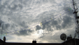
The Beverage antenna or "wave antenna" is a long-wire receiving antenna mainly used in the low frequency and medium frequency radio bands, invented by Harold H. Beverage in 1921. It is used by amateur radio, shortwave listening, and longwave radio DXers and military applications.
A guy-wire, guy-line, or guy-rope, also known as simply a guy, is a tensioned cable designed to add stability to a free-standing structure. They are used commonly in ship masts, radio masts, wind turbines, utility poles, fire service extension ladders used in church raises and tents. A thin vertical mast supported by guy wires is called a guyed mast. Structures that support antennas are frequently of a lattice construction and are called "towers". One end of the guy is attached to the structure, and the other is anchored to the ground at some distance from the mast or tower base. The tension in the diagonal guy-wire, combined with the compression and buckling strength of the structure, allows the structure to withstand lateral loads such as wind or the weight of cantilevered structures. They are installed radially, usually at equal angles about the structure, in trios and quads. As the tower leans a bit due to the wind force, the increased guy tension is resolved into a compression force in the tower or mast and a lateral force that resists the wind load. For example, antenna masts are often held up by three guy-wires at 120° angles. Structures with predictable lateral loads, such as electrical utility poles, may require only a single guy-wire to offset the lateral pull of the electrical wires, at a spot where the wires change direction.
A mast radiator is a radio mast or tower in which the entire structure functions as an antenna. This design, first used in radiotelegraphy stations in the early 1900s, is commonly used for transmitting antennas operating at low frequencies, in the VLF, LF and MF ranges, in particular those used for AM broadcasting. The metal mast is electrically connected to the transmitter. Its base is usually mounted on a nonconductive support to insulate it from the ground. A mast radiator is a form of monopole antenna.

A T-antenna, T-aerial, flat-top antenna, or top-hat antenna is a capacitively loaded monopole wire radio antenna used in the VLF, LF, MF and shortwave bands. T-antennas are widely used as transmitting antennas for amateur radio stations, long wave and medium wave broadcasting stations. They are also used as receiving antennas for shortwave listening.

The J-pole antenna, more properly known as the J antenna, was first invented by Hans Beggerow in 1909 for use in Zeppelin airships. Trailed behind the airship, it consisted of a single element, one half wavelength long radiator with a quarter wave parallel feedline tuning stub. This concept evolved to the J configuration by 1936 attaining the name J Antenna by 1943.
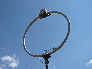
A loop antenna is a radio antenna consisting of a loop or coil of wire, tubing, or other electrical conductor usually fed by a balanced source or feeding a balanced load. Within this physical description there are two distinct antenna types. The large self-resonant loop antenna has a circumference close to one wavelength of the operating frequency and so is resonant at that frequency. This category also includes smaller loops 5% to 30% of a wavelength in circumference, which use a capacitor to make them resonant. These antennas are used for both transmission and reception. In contrast, small loop antennas less than 1% of a wavelength in size are very inefficient radiators, and so are only used for reception. An example is the ferrite (loopstick) antenna used in most AM broadcast radios. Loop antennas have a dipole radiation pattern; they are most sensitive to radio waves in two broad lobes in opposite directions, 180° apart. Due to this directional pattern they are used for radio direction finding (RDF), to locate the position of a transmitter.

A television antenna, or TV aerial, is an antenna specifically designed for the reception of over-the-air broadcast television signals, which are transmitted at frequencies from about 41 to 250 MHz in the VHF band, and 470 to 960 MHz in the UHF band in different countries. Television antennas are manufactured in two different types: "indoor" antennas, to be located on top of or next to the television set, and "outdoor" antennas, mounted on a mast on top of the owner's house. They can also be mounted in a loft or attic, where the dry conditions and increased elevation are advantageous for reception and antenna longevity. Outdoor antennas are more expensive and difficult to install, but are necessary for adequate reception in fringe areas far from television stations. The most common types of indoor antennas are the dipole and loop antennas, and for outdoor antennas the yagi, log periodic, and for UHF channels the multi-bay reflective array antenna.
Near vertical incidence skywave, or NVIS, is a skywave radio-wave propagation path that provides usable signals in the range between groundwave and conventional skywave distances—usually 30–400 miles (50–650 km). It is used for military and paramilitary communications, broadcasting, especially in the tropics, and by radio amateurs for nearby contacts circumventing line-of-sight barriers. The radio waves travel near-vertically upwards into the ionosphere, where they are refracted back down and can be received within a circular region up to 650 km from the transmitter. If the frequency is too high, refraction fails to occur and if it is too low, absorption in the ionospheric D layer may reduce the signal strength.
A monopole antenna is a class of radio antenna consisting of a straight rod-shaped conductor, often mounted perpendicularly over some type of conductive surface, called a ground plane. The driving signal from the transmitter is applied, or for receiving antennas the output signal to the receiver is taken, between the lower end of the monopole and the ground plane. One side of the antenna feedline is attached to the lower end of the monopole, and the other side is attached to the ground plane, which is often the Earth. This contrasts with a dipole antenna which consists of two identical rod conductors, with the signal from the transmitter applied between the two halves of the antenna.

An umbrella antenna is a top-loaded electrically lengthened monopole antenna, consisting in most cases of a mast fed at the ground end, to which a number of radial wires are connected at the top, sloping downwards. They are used as transmitting antennas below 1 MHz, in the LF and particularly the VLF bands, at frequencies sufficiently low that it is impractical or infeasible to build a full size quarter-wave monopole antenna.
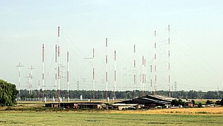
Curtain arrays are a class of large multielement directional wire radio transmitting antennas, used in the shortwave radio bands. They are a type of reflective array antenna, consisting of multiple wire dipole antennas, suspended in a vertical plane, often in front of a "curtain" reflector made of a flat vertical screen of many long parallel wires. These are suspended by support wires strung between pairs of tall steel towers, up to 300 ft (90 m) high. They are used for long-distance skywave transmission; they transmit a beam of radio waves at a shallow angle into the sky just above the horizon, which is reflected by the ionosphere back to Earth beyond the horizon. Curtain antennas are mostly used by international short wave radio stations to broadcast to large areas at transcontinental distances.
In radio systems, many different antenna types are used with specialized properties for particular applications. Antennas can be classified in various ways. The list below groups together antennas under common operating principles, following the way antennas are classified in many engineering textbooks.


