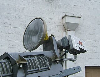
A feed horn is a small horn antenna used to couple a waveguide to e.g. a parabolic dish antenna or offset dish antenna for reception or transmission of microwaves. A typical application is the use for satellite television reception with a satellite dish. In that case the feed horn can either be a separate part used together with e.g. a "low-noise block downconverter" (LNB), or more typically today is integrated into a "low-noise block feedhorn" (LNBF).

A parabolicreflector is a reflective surface used to collect or project energy such as light, sound, or radio waves. Its shape is part of a circular paraboloid, that is, the surface generated by a parabola revolving around its axis. The parabolic reflector transforms an incoming plane wave travelling along the axis into a spherical wave converging toward the focus. Conversely, a spherical wave generated by a point source placed in the focus is reflected into a plane wave propagating as a collimated beam along the axis.
A satellite dish is a dish-shaped type of parabolic antenna designed to receive or transmit information by radio waves to or from a communication satellite. The term most commonly means a dish which receives direct-broadcast satellite television from a direct broadcast satellite in geostationary orbit.

A parabolic antenna is an antenna that uses a parabolic reflector, a curved surface with the cross-sectional shape of a parabola, to direct the radio waves. The most common form is shaped like a dish and is popularly called a dish antenna or parabolic dish. The main advantage of a parabolic antenna is that it has high directivity. It functions similarly to a searchlight or flashlight reflector to direct radio waves in a narrow beam, or receive radio waves from one particular direction only. Parabolic antennas have some of the highest gains, meaning that they can produce the narrowest beamwidths, of any antenna type. In order to achieve narrow beamwidths, the parabolic reflector must be much larger than the wavelength of the radio waves used, so parabolic antennas are used in the high frequency part of the radio spectrum, at UHF and microwave (SHF) frequencies, at which the wavelengths are small enough that conveniently sized reflectors can be used.

A reflecting telescope is a telescope that uses a single or a combination of curved mirrors that reflect light and form an image. The reflecting telescope was invented in the 17th century by Isaac Newton as an alternative to the refracting telescope which, at that time, was a design that suffered from severe chromatic aberration. Although reflecting telescopes produce other types of optical aberrations, it is a design that allows for very large diameter objectives. Almost all of the major telescopes used in astronomy research are reflectors. Many variant forms are in use and some employ extra optical elements to improve image quality or place the image in a mechanically advantageous position. Since reflecting telescopes use mirrors, the design is sometimes referred to as a catoptric telescope.

A directional antenna or beam antenna is an antenna which radiates or receives greater radio wave power in specific directions. Directional antennas can radiate radio waves in beams, when greater concentration of radiation in a certain direction is desired, or in receiving antennas receive radio waves from one specific direction only. This can increase the power transmitted to receivers in that direction, or reduce interference from unwanted sources. This contrasts with omnidirectional antennas such as dipole antennas which radiate radio waves over a wide angle, or receive from a wide angle.

The Newtonian telescope, also called the Newtonian reflector or just a Newtonian, is a type of reflecting telescope invented by the English scientist Sir Isaac Newton, using a concave primary mirror and a flat diagonal secondary mirror. Newton's first reflecting telescope was completed in 1668 and is the earliest known functional reflecting telescope. The Newtonian telescope's simple design has made it very popular with amateur telescope makers.

A horn antenna or microwave horn is an antenna that consists of a flaring metal waveguide shaped like a horn to direct radio waves in a beam. Horns are widely used as antennas at UHF and microwave frequencies, above 300 MHz. They are used as feed antennas for larger antenna structures such as parabolic antennas, as standard calibration antennas to measure the gain of other antennas, and as directive antennas for such devices as radar guns, automatic door openers, and microwave radiometers. Their advantages are moderate directivity, broad bandwidth, low losses, and simple construction and adjustment.

A catadioptric optical system is one where refraction and reflection are combined in an optical system, usually via lenses (dioptrics) and curved mirrors (catoptrics). Catadioptric combinations are used in focusing systems such as searchlights, headlamps, early lighthouse focusing systems, optical telescopes, microscopes, and telephoto lenses. Other optical systems that use lenses and mirrors are also referred to as "catadioptric", such as surveillance catadioptric sensors.
The Schmidt–Cassegrain is a catadioptric telescope that combines a Cassegrain reflector's optical path with a Schmidt corrector plate to make a compact astronomical instrument that uses simple spherical surfaces.

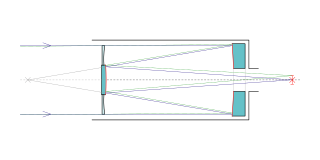
The Cassegrain reflector is a combination of a primary concave mirror and a secondary convex mirror, often used in optical telescopes and radio antennas, the main characteristic being that the optical path folds back onto itself, relative to the optical system's primary mirror entrance aperture. This design puts the focal point at a convenient location behind the primary mirror and the convex secondary adds a telephoto effect creating a much longer focal length in a mechanically short system.

An antenna reflector is a device that reflects electromagnetic waves. Antenna reflectors can exist as a standalone device for redirecting radio frequency (RF) energy, or can be integrated as part of an antenna assembly.

An offset dish antenna or off-axis dish antenna is a type of parabolic antenna. It is so called because the antenna feed is offset to the side of the reflector, in contrast to the common "front-feed" parabolic antenna where the feed antenna is suspended in front of the dish, on its axis. As in a front-fed parabolic dish, the feed is located at the focal point of the reflector, but the reflector is an asymmetric segment of a paraboloid, so the focus is located to the side.

The Medicina Radio Observatory is an astronomical observatory located 30 km from Bologna, Italy. It is operated by the Institute for Radio Astronomy of the National Institute for Astrophysics (INAF) of the government of Italy.

A focal cloud is the collection of focal points of an imperfect lens or parabolic reflector whether optical, electrostatic or electromagnetic. This includes parabolic antennas and lens-type reflective antennas of all kinds. The effect is analogous to the circle of confusion in photography.
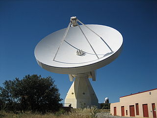
The Yebes Observatory RT40m, or ARIESXXI, is a radio telescope which is part of the observatory at Yebes, Spain. It is a 40-metre Cassegrain–Nasmyth telescope.
A beam waveguide antenna is a particular type of antenna dish, at which waveguides are used to transmit the radio beam between the large steerable dish and the equipment for reception or transmission, like e.g. RF power amplifiers.

An antenna array is a set of multiple connected antennas which work together as a single antenna, to transmit or receive radio waves. The individual antennas are usually connected to a single receiver or transmitter by feedlines that feed the power to the elements in a specific phase relationship. The radio waves radiated by each individual antenna combine and superpose, adding together to enhance the power radiated in desired directions, and cancelling to reduce the power radiated in other directions. Similarly, when used for receiving, the separate radio frequency currents from the individual antennas combine in the receiver with the correct phase relationship to enhance signals received from the desired directions and cancel signals from undesired directions. More sophisticated array antennas may have multiple transmitter or receiver modules, each connected to a separate antenna element or group of elements.
Fresnel zone antennas are antennas that focus the signal by using the phase shifting property of the antenna surface or its shape. There are several types of Fresnel zone antennas, namely, Fresnel zone plate, offset Fresnel zone plate antennas, phase correcting reflective array or "Reflectarray" antennas and 3 Dimensional Fresnel antennas. They are a class of diffractive antennas and have been used from radio frequencies to X rays.
The Leighton Radio Telescopes are 10.4 meter parabolic dish antennas designed by Robert B. Leighton in the 1970s, which were fabricated on the Caltech campus during the 1970s and 1980s. The telescope surfaces reached an accuracy of 10 microns RMS, allowing observations throughout the millimeter and submillimeter bands. In all, eight of these telescopes were made. They were used as the six elements of the Owens Valley Radio Observatory (OVRO) millimeter interferometer in California, and as single telescopes at the Caltech Submillimeter Observatory in Hawaii and the Raman Research Institute (RRI) at Bangalore, India. In the spring of 2005, the six Leighton telescopes in Owens Valley were moved to a high mountain site in the White Mountains to form the core of the CARMA array of 25 telescopes. The CARMA array was decommissioned in 2015 at which time the Leighton telescopes were moved back to OVRO, where they are now being repurposed for different projects including the CO Mapping Array Pathfinder (COMAP), the Event Horizon Telescope (EHT), and various transient detection projects.


