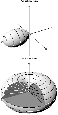
In the field of antenna design the term radiation pattern refers to the directional (angular) dependence of the strength of the radio waves from the antenna or other source.
In measurement technology and metrology, calibration is the comparison of measurement values delivered by a device under test with those of a calibration standard of known accuracy. Such a standard could be another measurement device of known accuracy, a device generating the quantity to be measured such as a voltage, a sound tone, or a physical artifact, such as a meter ruler.
In electromagnetics, an antenna's gain is a key performance parameter which combines the antenna's directivity and radiation efficiency. The term power gain has been deprecated by IEEE. In a transmitting antenna, the gain describes how well the antenna converts input power into radio waves headed in a specified direction. In a receiving antenna, the gain describes how well the antenna converts radio waves arriving from a specified direction into electrical power. When no direction is specified, gain is understood to refer to the peak value of the gain, the gain in the direction of the antenna's main lobe. A plot of the gain as a function of direction is called the antenna pattern or radiation pattern. It is not to be confused with directivity, which does not take an antenna's radiation efficiency into account.

In radio engineering, an antenna or aerial is the interface between radio waves propagating through space and electric currents moving in metal conductors, used with a transmitter or receiver. In transmission, a radio transmitter supplies an electric current to the antenna's terminals, and the antenna radiates the energy from the current as electromagnetic waves. In reception, an antenna intercepts some of the power of a radio wave in order to produce an electric current at its terminals, that is applied to a receiver to be amplified. Antennas are essential components of all radio equipment.

The near field and far field are regions of the electromagnetic (EM) field around an object, such as a transmitting antenna, or the result of radiation scattering off an object. Non-radiative near-field behaviors dominate close to the antenna or scattering object, while electromagnetic radiation far-field behaviors dominate at greater distances.

A Yagi–Uda antenna, or simply Yagi antenna, is a directional antenna consisting of two or more parallel resonant antenna elements in an end-fire array; these elements are most often metal rods acting as half-wave dipoles. Yagi–Uda antennas consist of a single driven element connected to a radio transmitter and/or receiver through a transmission line, and additional "passive radiators" with no electrical connection, usually including one so-called reflector and any number of directors. It was invented in 1926 by Shintaro Uda of Tohoku Imperial University, Japan, with a lesser role played by his boss Hidetsugu Yagi.

An anechoic chamber is a room designed to stop reflections of either sound or electromagnetic waves. They are also often isolated from energy entering from their surroundings. This combination means that a person or detector exclusively hears direct sounds, in effect simulating being outside in a free field.

Direction finding (DF), or radio direction finding (RDF), is – in accordance with International Telecommunication Union (ITU) – defined as radio location that uses the reception of radio waves to determine the direction in which a radio station or an object is located. This can refer to radio or other forms of wireless communication, including radar signals detection and monitoring (ELINT/ESM). By combining the direction information from two or more suitably spaced receivers, the source of a transmission may be located via triangulation. Radio direction finding is used in the navigation of ships and aircraft, to locate emergency transmitters for search and rescue, for tracking wildlife, and to locate illegal or interfering transmitters. RDF was important in combating German threats during both the World War II Battle of Britain and the long running Battle of the Atlantic. In the former, the Air Ministry also used RDF to locate its own fighter groups and vector them to detected German raids.

An antenna reflector is a device that reflects electromagnetic waves. Antenna reflectors can exist as a standalone device for redirecting radio frequency (RF) energy, or can be integrated as part of an antenna assembly.
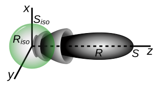
An isotropic radiator is a theoretical point source of electromagnetic or sound waves which radiates the same intensity of radiation in all directions. It has no preferred direction of radiation. It radiates uniformly in all directions over a sphere centred on the source. Isotropic radiators are used as reference radiators with which other sources are compared, for example in determining the gain of antennas. A coherent isotropic radiator of electromagnetic waves is theoretically impossible, but incoherent radiators can be built. An isotropic sound radiator is possible because sound is a longitudinal wave.

A network analyzer is an instrument that measures the network parameters of electrical networks. Today, network analyzers commonly measure s–parameters because reflection and transmission of electrical networks are easy to measure at high frequencies, but there are other network parameter sets such as y-parameters, z-parameters, and h-parameters. Network analyzers are often used to characterize two-port networks such as amplifiers and filters, but they can be used on networks with an arbitrary number of ports.
Antenna measurement techniques refers to the testing of antennas to ensure that the antenna meets specifications or simply to characterize it. Typical parameters of antennas are gain, bandwidth, radiation pattern, beamwidth, polarization, and impedance.
Robot calibration is a process used to improve the accuracy of robots, particularly industrial robots which are highly repeatable but not accurate. Robot calibration is the process of identifying certain parameters in the kinematic structure of an industrial robot, such as the relative position of robot links. Depending on the type of errors modeled, the calibration can be classified in three different ways. Level-1 calibration only models differences between actual and reported joint displacement values,. Level-2 calibration, also known as kinematic calibration, concerns the entire geometric robot calibration which includes angle offsets and joint lengths. Level-3 calibration, also called a non-kinematic calibration, models errors other than geometric defaults such as stiffness, joint compliance, and friction. Often Level-1 and Level-2 calibration are sufficient for most practical needs.
Monopulse radar is a radar system that uses additional encoding of the radio signal to provide accurate directional information. The name refers to its ability to extract range and direction from a single signal pulse.

The Numerical Electromagnetics Code, or NEC, is a popular antenna modeling system for wire and surface antennas. It was originally written in FORTRAN during the 1970s by Gerald Burke and Andrew Poggio of the Lawrence Livermore National Laboratory. The code was made publicly available for general use and has subsequently been distributed for many computer platforms from mainframes to PCs.
The Downrange Anti-missile Measurement Program or DAMP was an applied research project to obtain scientific data, just prior to and during re-entry, on intermediate- and intercontinental-range ballistic missiles as they returned to earth. The program was funded by the Advanced Research Projects Agency (ARPA) under the technical direction of the Army Ordnance Missile Command (AOMC) during the period 1 January 1959 through 30 September 1963.
EMF measurements are measurements of ambient (surrounding) electromagnetic fields that are performed using particular sensors or probes, such as EMF meters. These probes can be generally considered as antennas although with different characteristics. In fact, probes should not perturb the electromagnetic field and must prevent coupling and reflection as much as possible in order to obtain precise results. There are two main types of EMF measurements:

A measuring instrument is a device to measure a physical quantity. In the physical sciences, quality assurance, and engineering, measurement is the activity of obtaining and comparing physical quantities of real-world objects and events. Established standard objects and events are used as units, and the process of measurement gives a number relating the item under study and the referenced unit of measurement. Measuring instruments, and formal test methods which define the instrument's use, are the means by which these relations of numbers are obtained. All measuring instruments are subject to varying degrees of instrument error and measurement uncertainty. These instruments may range from simple objects such as rulers and stopwatches to electron microscopes and particle accelerators. Virtual instrumentation is widely used in the development of modern measuring instruments.
Flow conditioning ensures that the “real world” environment closely resembles the “laboratory” environment for proper performance of inferential flowmeters like orifice, turbine, coriolis, ultrasonic etc.

Slotted lines are used for microwave measurements and consist of a movable probe inserted into a slot in a transmission line. They are used in conjunction with a microwave power source and usually, in keeping with their low-cost application, a low cost Schottky diode detector and VSWR meter rather than an expensive microwave power meter.