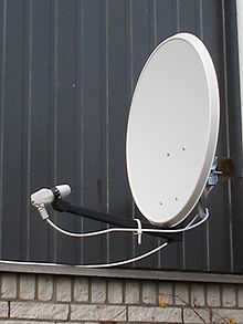
An offset dish antenna or off-axis dish antenna is a type of parabolic antenna. It is so called because the antenna feed is offset to the side of the reflector, in contrast to the common "front-feed" parabolic antenna where the feed antenna is suspended in front of the dish, on its axis. As in a front-fed parabolic dish, the feed is located at the focal point of the reflector, but the reflector is an asymmetric segment of a paraboloid, so the focus is located to the side.
The purpose of this design is to move the feed antenna and its supports out of the path of the incoming radio waves. In an ordinary front-fed dish antenna, the feed structure and its supports are located in the path of the incoming beam of radio waves, partially obstructing them, casting a "shadow" on the dish, reducing the radio power received. In technical terms this reduces the aperture efficiency of the antenna, reducing its gain. In the offset design, the feed is positioned outside the area of the beam, usually below it on a boom sticking out from the bottom edge of the dish. The beam axis of the antenna, the axis of the incoming or outgoing radio waves, is skewed at an angle to the plane of the dish mouth.
The design is most widely used for small parabolic antennas or "mini-dishes", such as common Ku band home satellite television dishes, where the feed structure is large enough in relation to the dish to block a significant proportion of the signal. Another application is on satellites, particularly the direct broadcast satellites which use parabolic dishes to beam television signals to homes on Earth. Because of the limited transmitter power provided by their solar cells, satellite antennas must function as efficiently as possible. The offset design is also widely used in radar antennas. These must collect as much signal as possible in order to detect faint return signals from faraway targets.
Offset dish antennas are more difficult to design than front-fed antennas because the dish is an asymmetric segment of a paraboloid with different curvatures in the two axes. Before the 1970s offset designs were mostly limited to radar antennas, which required asymmetric reflectors anyway to create shaped beams. The advent in the 1970s of computer design tools which could easily calculate the radiation pattern of offset dishes has removed this limitation, and efficient offset designs are being used more and more widely in recent years.
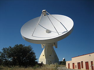
In telecommunications and radar, a Cassegrain antenna is a parabolic antenna in which the feed antenna is mounted at or behind the surface of the concave main parabolic reflector dish and is aimed at a smaller convex secondary reflector suspended in front of the primary reflector. The beam of radio waves from the feed illuminates the secondary reflector, which reflects it back to the main reflector dish, which reflects it forward again to form the desired beam. The Cassegrain design is widely used in parabolic antennas, particularly in large antennas such as those in satellite ground stations, radio telescopes, and communication satellites.
In telecommunications and radar, a reflective array antenna is a class of directive antennas in which multiple driven elements are mounted in front of a flat surface designed to reflect the radio waves in a desired direction. They are a type of array antenna. They are often used in the VHF and UHF frequency bands. VHF examples are generally large and resemble a highway billboard, so they are sometimes called billboard antennas. Other names are bedspring array and bowtie array depending on the type of elements making up the antenna. The curtain array is a larger version used by shortwave radio broadcasting stations.
A radio telescope is a specialized antenna and radio receiver used to detect radio waves from astronomical radio sources in the sky. Radio telescopes are the main observing instrument used in radio astronomy, which studies the radio frequency portion of the electromagnetic spectrum emitted by astronomical objects, just as optical telescopes are the main observing instrument used in traditional optical astronomy which studies the light wave portion of the spectrum coming from astronomical objects. Unlike optical telescopes, radio telescopes can be used in the daytime as well as at night.
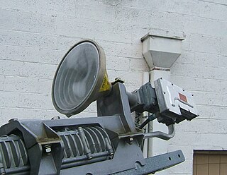
A feed horn is a small horn antenna used to couple a waveguide to e.g. a parabolic dish antenna or offset dish antenna for reception or transmission of microwaves. A typical application is the use for satellite television reception with a satellite dish. In that case the feed horn can either be a separate part used together with e.g. a "low-noise block downconverter" (LNB), or more typically today is integrated into a "low-noise block feedhorn" (LNBF).
In radio engineering, an antenna or aerial is an electronic device that converts an alternating electric current into radio waves (transmitting), or radio waves into an electric current (receiving). It is the interface between radio waves propagating through space and electric currents moving in metal conductors, used with a transmitter or receiver. In transmission, a radio transmitter supplies an electric current to the antenna's terminals, and the antenna radiates the energy from the current as electromagnetic waves. In reception, an antenna intercepts some of the power of a radio wave in order to produce an electric current at its terminals, that is applied to a receiver to be amplified. Antennas are essential components of all radio equipment.
A parabolicreflector is a reflective surface used to collect or project energy such as light, sound, or radio waves. Its shape is part of a circular paraboloid, that is, the surface generated by a parabola revolving around its axis. The parabolic reflector transforms an incoming plane wave travelling along the axis into a spherical wave converging toward the focus. Conversely, a spherical wave generated by a point source placed in the focus is reflected into a plane wave propagating as a collimated beam along the axis.
A satellite dish is a dish-shaped type of parabolic antenna designed to receive or transmit information by radio waves to or from a communication satellite. The term most commonly means a dish which receives direct-broadcast satellite television from a direct broadcast satellite in geostationary orbit.
A parabolic antenna is an antenna that uses a parabolic reflector, a curved surface with the cross-sectional shape of a parabola, to direct the radio waves. The most common form is shaped like a dish and is popularly called a dish antenna or parabolic dish. The main advantage of a parabolic antenna is that it has high directivity. It functions similarly to a searchlight or flashlight reflector to direct radio waves in a narrow beam, or receive radio waves from one particular direction only. Parabolic antennas have some of the highest gains, meaning that they can produce the narrowest beamwidths, of any antenna type. In order to achieve narrow beamwidths, the parabolic reflector must be much larger than the wavelength of the radio waves used, so parabolic antennas are used in the high frequency part of the radio spectrum, at UHF and microwave (SHF) frequencies, at which the wavelengths are small enough that conveniently sized reflectors can be used.
A directional antenna or beam antenna is an antenna which radiates or receives greater radio wave power in specific directions. Directional antennas can radiate radio waves in beams, when greater concentration of radiation in a certain direction is desired, or in receiving antennas receive radio waves from one specific direction only. This can increase the power transmitted to receivers in that direction, or reduce interference from unwanted sources. This contrasts with omnidirectional antennas such as dipole antennas which radiate radio waves over a wide angle, or receive from a wide angle.
A horn antenna or microwave horn is an antenna that consists of a flaring metal waveguide shaped like a horn to direct radio waves in a beam. Horns are widely used as antennas at UHF and microwave frequencies, above 300 MHz. They are used as feed antennas for larger antenna structures such as parabolic antennas, as standard calibration antennas to measure the gain of other antennas, and as directive antennas for such devices as radar guns, automatic door openers, and microwave radiometers. Their advantages are moderate directivity, broad bandwidth, low losses, and simple construction and adjustment.
An antenna reflector is a device that reflects electromagnetic waves. Antenna reflectors can exist as a standalone device for redirecting radio frequency (RF) energy, or can be integrated as part of an antenna assembly.
A radio transmitter or receiver is connected to an antenna which emits or receives the radio waves. The antenna feed system or antenna feed is the cable or conductor, and other associated equipment, which connects the transmitter or receiver with the antenna and makes the two devices compatible. In a radio transmitter, the transmitter generates an alternating current of radio frequency, and the feed system feeds the current to the antenna, which converts the power in the current to radio waves. In a radio receiver, the incoming radio waves excite tiny alternating currents in the antenna, and the feed system delivers this current to the receiver, which processes the signal.
A turnstile antenna, or crossed-dipole antenna, is a radio antenna consisting of a set of two identical dipole antennas mounted at right angles to each other and fed in phase quadrature; the two currents applied to the dipoles are 90° out of phase. The name reflects the notion the antenna looks like a turnstile when mounted horizontally. The antenna can be used in two possible modes. In normal mode the antenna radiates horizontally polarized radio waves perpendicular to its axis. In axial mode the antenna radiates circularly polarized radiation along its axis.
A focal cloud is the collection of focal points of an imperfect lens or parabolic reflector whether optical, electrostatic or electromagnetic. This includes parabolic antennas and lens-type reflective antennas of all kinds. The effect is analogous to the circle of confusion in photography.
The Yebes Observatory RT40m, or ARIESXXI, is a radio telescope which is part of the observatory at Yebes, Spain. It is a 40-metre Cassegrain–Nasmyth telescope.
A beam waveguide antenna is a particular type of antenna dish, at which waveguides are used to transmit the radio beam between the large steerable dish and the equipment for reception or transmission, like e.g. RF power amplifiers.
An antenna array is a set of multiple connected antennas which work together as a single antenna, to transmit or receive radio waves. The individual antennas are usually connected to a single receiver or transmitter by feedlines that feed the power to the elements in a specific phase relationship. The radio waves radiated by each individual antenna combine and superpose, adding together to enhance the power radiated in desired directions, and cancelling to reduce the power radiated in other directions. Similarly, when used for receiving, the separate radio frequency currents from the individual antennas combine in the receiver with the correct phase relationship to enhance signals received from the desired directions and cancel signals from undesired directions. More sophisticated array antennas may have multiple transmitter or receiver modules, each connected to a separate antenna element or group of elements.
The Type 277 was a surface search and secondary aircraft early warning radar used by the Royal Navy and allies during World War II and the post-war era. It was a major update of the earlier Type 271 radar, offering much more power, better signal processing, new displays, and new antennas with greatly improved performance and much simpler mounting requirements. It allowed a radar with performance formerly found only on cruisers and battleships to be fitted even to the smallest corvettes. It began to replace the 271 in 1943 and was widespread by the end of the year.
In radio systems, many different antenna types are used whose properties are especially crafted for particular applications.
The cheese antenna, also known as a pillbox antenna, is a type of microwave-frequency parabolic antenna used in certain types of radar. The antenna consists of a cylindrical parabolic reflector consisting of sheet metal with a parabolic curve in one dimension and flat in the other, with metal plates covering the open sides, and a feed antenna, almost always some sort of feed horn, in front, pointing back toward the reflector. When the antenna is wide along its flat axis it is called a pillbox antenna and when narrow a cheese antenna. The name comes from the resulting antenna looking like a segment that has been cut from a wheel of cheese.
This page is based on this Wikipedia article Text is available under the CC BY-SA 4.0 license; additional terms may apply. Images, videos and audio are available under their respective licenses.