
Microwave is a form of electromagnetic radiation with wavelengths shorter than other radio waves but longer than infrared waves. Its wavelength ranges from about one meter to one millimeter, corresponding to frequencies between 300 MHz and 300 GHz, broadly construed. A more common definition in radio-frequency engineering is the range between 1 and 100 GHz, or between 1 and 3000 GHz . The prefix micro- in microwave is not meant to suggest a wavelength in the micrometer range; rather, it indicates that microwaves are small, compared to the radio waves used in prior radio technology.

Radar is a system that uses radio waves to determine the distance (ranging), direction, and radial velocity of objects relative to the site. It is a radiodetermination method used to detect and track aircraft, ships, spacecraft, guided missiles, motor vehicles, map weather formations, and terrain.

In telecommunications and radar, a Cassegrain antenna is a parabolic antenna in which the feed antenna is mounted at or behind the surface of the concave main parabolic reflector dish and is aimed at a smaller convex secondary reflector suspended in front of the primary reflector. The beam of radio waves from the feed illuminates the secondary reflector, which reflects it back to the main reflector dish, which reflects it forward again to form the desired beam. The Cassegrain design is widely used in parabolic antennas, particularly in large antennas such as those in satellite ground stations, radio telescopes, and communication satellites.

In telecommunications and radar, a reflective array antenna is a class of directive antennas in which multiple driven elements are mounted in front of a flat surface designed to reflect the radio waves in a desired direction. They are a type of array antenna. They are often used in the VHF and UHF frequency bands. VHF examples are generally large and resemble a highway billboard, so they are sometimes called billboard antennas. Other names are bedspring array and bowtie array depending on the type of elements making up the antenna. The curtain array is a larger version used by shortwave radio broadcasting stations.

A radio telescope is a specialized antenna and radio receiver used to detect radio waves from astronomical radio sources in the sky. Radio telescopes are the main observing instrument used in radio astronomy, which studies the radio frequency portion of the electromagnetic spectrum, just as optical telescopes are used to make observations in the visible portion of the spectrum in traditional optical astronomy. Unlike optical telescopes, radio telescopes can be used in the daytime as well as at night.

High frequency (HF) is the ITU designation for the band of radio waves with frequency between 3 and 30 megahertz (MHz). It is also known as the decameter band or decameter wave as its wavelengths range from one to ten decameters. Frequencies immediately below HF are denoted medium frequency (MF), while the next band of higher frequencies is known as the very high frequency (VHF) band. The HF band is a major part of the shortwave band of frequencies, so communication at these frequencies is often called shortwave radio. Because radio waves in this band can be reflected back to Earth by the ionosphere layer in the atmosphere – a method known as "skip" or "skywave" propagation – these frequencies can be used for long-distance communication across intercontinental distances and for mountainous terrains which prevent line-of-sight communications. The band is used by international shortwave broadcasting stations (3.95–25.82 MHz), aviation communication, government time stations, weather stations, amateur radio and citizens band services, among other uses.

A parabolic antenna is an antenna that uses a parabolic reflector, a curved surface with the cross-sectional shape of a parabola, to direct the radio waves. The most common form is shaped like a dish and is popularly called a dish antenna or parabolic dish. The main advantage of a parabolic antenna is that it has high directivity. It functions similarly to a searchlight or flashlight reflector to direct radio waves in a narrow beam, or receive radio waves from one particular direction only. Parabolic antennas have some of the highest gains, meaning that they can produce the narrowest beamwidths, of any antenna type. In order to achieve narrow beamwidths, the parabolic reflector must be much larger than the wavelength of the radio waves used, so parabolic antennas are used in the high frequency part of the radio spectrum, at UHF and microwave (SHF) frequencies, at which the wavelengths are small enough that conveniently sized reflectors can be used.
The 2-meter amateur radio band is a portion of the VHF radio spectrum that comprises frequencies stretching from 144 MHz to 148 MHz in International Telecommunication Union region (ITU) Regions 2 and 3 and from 144 MHz to 146 MHz in ITU Region 1 . The license privileges of amateur radio operators include the use of frequencies within this band for telecommunication, usually conducted locally with a line-of-sight range of about 100 miles (160 km).

Direction finding (DF), or radio direction finding (RDF), is the use of radio waves to determine the direction to a radio source. The source may be a cooperating radio transmitter or may be an inadvertant source, a naturally-occurring radio source, or an illicit or enemy system. Radio direction finding differs from radar in that only the direction is determined by any one receiver; a radar system usually also gives a distance to the object of interest, as well as direction. By triangulation, the location of a radio source can be determined by measuring its direction from two or more locations. Radio direction finding is used in radio navigation for ships and aircraft, to locate emergency transmitters for search and rescue, for tracking wildlife, and to locate illegal or interfering transmitters. During the Second World War, radio direction finding was used by both sides to locate and direct aircraft, surface ships, and submarines.
An active electronically scanned array (AESA) is a type of phased array antenna, which is a computer-controlled antenna array in which the beam of radio waves can be electronically steered to point in different directions without moving the antenna. In the AESA, each antenna element is connected to a small solid-state transmit/receive module (TRM) under the control of a computer, which performs the functions of a transmitter and/or receiver for the antenna. This contrasts with a passive electronically scanned array (PESA), in which all the antenna elements are connected to a single transmitter and/or receiver through phase shifters under the control of the computer. AESA's main use is in radar, and these are known as active phased array radar (APAR).

The Beverage antenna or "wave antenna" is a long-wire receiving antenna mainly used in the low frequency and medium frequency radio bands, invented by Harold H. Beverage in 1921. It is used by amateur radio operators, shortwave listeners, longwave radio DXers and for military applications.
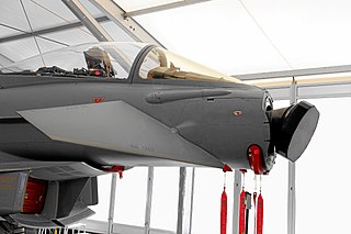
Plasma stealth is a proposed process to use ionized gas (plasma) to reduce the radar cross-section (RCS) of an aircraft. Interactions between electromagnetic radiation and ionized gas have been extensively studied for many purposes, including concealing aircraft from radar as stealth technology. Various methods might plausibly be able to form a layer or cloud of plasma around a vehicle to deflect or absorb radar, from simpler electrostatic or radio frequency discharges to more complex laser discharges. It is theoretically possible to reduce RCS in this way, but it may be very difficult to do so in practice. Some Russian missiles e.g. the 3M22 Zircon (SS-N-33) and Kh-47M2 Kinzhal missiles have been reported to make use of plasma stealth.

A passive electronically scanned array (PESA), also known as passive phased array, is an antenna in which the beam of radio waves can be electronically steered to point in different directions, in which all the antenna elements are connected to a single transmitter and/or receiver. The largest use of phased arrays is in radars. Most phased array radars in the world are PESA. The civilian microwave landing system uses PESA transmit-only arrays.
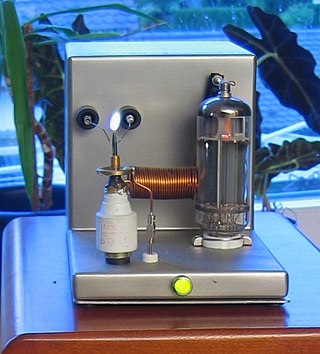
Plasma speakers or ionophones are a form of loudspeaker which varies air pressure via an electrical plasma instead of a solid diaphragm. The plasma arc heats the surrounding air causing it to expand. Varying the electrical signal that drives the plasma and connected to the output of an audio amplifier, the plasma size varies which in turn varies the expansion of the surrounding air creating sound waves.

Plasma-enhanced chemical vapor deposition (PECVD) is a chemical vapor deposition process used to deposit thin films from a gas state (vapor) to a solid state on a substrate. Chemical reactions are involved in the process, which occur after creation of a plasma of the reacting gases. The plasma is generally created by radio frequency (RF) alternating current (AC) frequency or direct current (DC) discharge between two electrodes, the space between which is filled with the reacting gases.
An antenna array is a set of multiple connected antennas which work together as a single antenna, to transmit or receive radio waves. The individual antennas are usually connected to a single receiver or transmitter by feedlines that feed the power to the elements in a specific phase relationship. The radio waves radiated by each individual antenna combine and superpose, adding together to enhance the power radiated in desired directions, and cancelling to reduce the power radiated in other directions. Similarly, when used for receiving, the separate radio frequency currents from the individual antennas combine in the receiver with the correct phase relationship to enhance signals received from the desired directions and cancel signals from undesired directions. More sophisticated array antennas may have multiple transmitter or receiver modules, each connected to a separate antenna element or group of elements.
Fresnel zone antennas are antennas that focus the signal by using the phase shifting property of the antenna surface or its shape. There are several types of Fresnel zone antennas, namely, Fresnel zone plate, offset Fresnel zone plate antennas, phase correcting reflective array or "Reflectarray" antennas and 3 Dimensional Fresnel antennas. They are a class of diffractive antennas and have been used from radio frequencies to X rays.
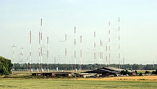
Curtain arrays are a class of large multielement directional radio transmitting wire antennas, used in the short-wave radio bands. They constitute a type of reflective array antenna, consisting of multiple wire dipole antennas, suspended in a vertical plane, often positioned in front of a "curtain" reflector made of a flat vertical screen of many long parallel wires. These are suspended by support wires strung between pairs of tall steel towers, reaching heights of up to 90 m high. Primarily employed for long-distance skywave transmission, they emit a beam of radio waves at a shallow angle into the sky just above the horizon, which is then reflected by the ionosphere back to Earth beyond the horizon. Curtain arrays are extensively used by international short-wave radio stations for broadcasting to large areas at transcontinental distances.
The first smart antennas were developed for military communications and intelligence gathering. The growth of cellular telephone in the 1980s attracted interest in commercial applications. The upgrade to digital radio technology in the mobile phone, indoor wireless network, and satellite broadcasting industries created new opportunities for smart antennas in the 1990s, culminating in the development of the MIMO technology used in 4G wireless networks.
