A viscometer is an instrument used to measure the viscosity of a fluid. For liquids with viscosities which vary with flow conditions, an instrument called a rheometer is used. Thus, a rheometer can be considered as a special type of viscometer. Viscometers can measure only constant viscosity, that is, viscosity that does not change with flow conditions.

The electrical resistance of an object is a measure of its opposition to the flow of electric current. Its reciprocal quantity is electrical conductance, measuring the ease with which an electric current passes. Electrical resistance shares some conceptual parallels with mechanical friction. The SI unit of electrical resistance is the ohm, while electrical conductance is measured in siemens (S).
In engineering, deformation refers to the change in size or shape of an object. Displacements are the absolute change in position of a point on the object. Deflection is the relative change in external displacements on an object. Strain is the relative internal change in shape of an infinitesimally small cube of material and can be expressed as a non-dimensional change in length or angle of distortion of the cube. Strains are related to the forces acting on the cube, which are known as stress, by a stress-strain curve. The relationship between stress and strain is generally linear and reversible up until the yield point and the deformation is elastic. The linear relationship for a material is known as Young's modulus. Above the yield point, some degree of permanent distortion remains after unloading and is termed plastic deformation. The determination of the stress and strain throughout a solid object is given by the field of strength of materials and for a structure by structural analysis.

In materials science, fatigue is the initiation and propagation of cracks in a material due to cyclic loading. Once a fatigue crack has initiated, it grows a small amount with each loading cycle, typically producing striations on some parts of the fracture surface. The crack will continue to grow until it reaches a critical size, which occurs when the stress intensity factor of the crack exceeds the fracture toughness of the material, producing rapid propagation and typically complete fracture of the structure.
In metallurgy, a shape-memory alloy (SMA) is an alloy that can be deformed when cold but returns to its pre-deformed ("remembered") shape when heated. It is also known in other names such as memory metal, memory alloy, smart metal, smart alloy, and muscle wire. The "memorized geometry" can be modified by fixating the desired geometry and subjecting it to a thermal treatment, for example a wire can be taught to memorize the shape of a coil spring.

In materials science, creep is the tendency of a solid material to undergo slow deformation while subject to persistent mechanical stresses. It can occur as a result of long-term exposure to high levels of stress that are still below the yield strength of the material. Creep is more severe in materials that are subjected to heat for long periods and generally increase as they near their melting point.
In materials science and continuum mechanics, viscoelasticity is the property of materials that exhibit both viscous and elastic characteristics when undergoing deformation. Viscous materials, like water, resist shear flow and strain linearly with time when a stress is applied. Elastic materials strain when stretched and immediately return to their original state once the stress is removed.

Soil mechanics is a branch of soil physics and applied mechanics that describes the behavior of soils. It differs from fluid mechanics and solid mechanics in the sense that soils consist of a heterogeneous mixture of fluids and particles but soil may also contain organic solids and other matter. Along with rock mechanics, soil mechanics provides the theoretical basis for analysis in geotechnical engineering, a subdiscipline of civil engineering, and engineering geology, a subdiscipline of geology. Soil mechanics is used to analyze the deformations of and flow of fluids within natural and man-made structures that are supported on or made of soil, or structures that are buried in soils. Example applications are building and bridge foundations, retaining walls, dams, and buried pipeline systems. Principles of soil mechanics are also used in related disciplines such as geophysical engineering, coastal engineering, agricultural engineering, hydrology and soil physics.

In materials science, work hardening, also known as strain hardening, is the strengthening of a metal or polymer by plastic deformation. Work hardening may be desirable, undesirable, or inconsequential, depending on the context.

A rheometer is a laboratory device used to measure the way in which a viscous fluid flows in response to applied forces. It is used for those fluids which cannot be defined by a single value of viscosity and therefore require more parameters to be set and measured than is the case for a viscometer. It measures the rheology of the fluid.
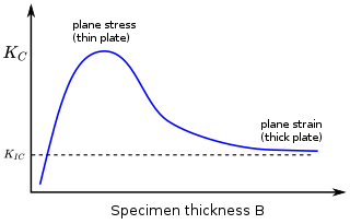
In materials science, fracture toughness is the critical stress intensity factor of a sharp crack where propagation of the crack suddenly becomes rapid and unlimited. A component's thickness affects the constraint conditions at the tip of a crack with thin components having plane stress conditions and thick components having plane strain conditions. Plane strain conditions give the lowest fracture toughness value which is a material property. The critical value of stress intensity factor in mode I loading measured under plane strain conditions is known as the plane strain fracture toughness, denoted . When a test fails to meet the thickness and other test requirements that are in place to ensure plane strain conditions, the fracture toughness value produced is given the designation . Fracture toughness is a quantitative way of expressing a material's resistance to crack propagation and standard values for a given material are generally available.
Nanoindentation, also called instrumented indentation testing, is a variety of indentation hardness tests applied to small volumes. Indentation is perhaps the most commonly applied means of testing the mechanical properties of materials. The nanoindentation technique was developed in the mid-1970s to measure the hardness of small volumes of material.
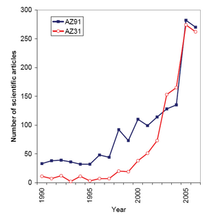
Magnesium alloys are mixtures of magnesium with other metals, often aluminium, zinc, manganese, silicon, copper, rare earths and zirconium. Magnesium alloys have a hexagonal lattice structure, which affects the fundamental properties of these alloys. Plastic deformation of the hexagonal lattice is more complicated than in cubic latticed metals like aluminium, copper and steel; therefore, magnesium alloys are typically used as cast alloys, but research of wrought alloys has been more extensive since 2003. Cast magnesium alloys are used for many components of modern automobiles and have been used in some high-performance vehicles; die-cast magnesium is also used for camera bodies and components in lenses.
Thermomechanical analysis (TMA) is a technique used in thermal analysis, a branch of materials science which studies the properties of materials as they change with temperature.
The Larson–Miller relation, also widely known as the Larson–Miller parameter and often abbreviated LMP, is a parametric relation used to extrapolate experimental data on creep and rupture life of engineering materials.

Viscoplasticity is a theory in continuum mechanics that describes the rate-dependent inelastic behavior of solids. Rate-dependence in this context means that the deformation of the material depends on the rate at which loads are applied. The inelastic behavior that is the subject of viscoplasticity is plastic deformation which means that the material undergoes unrecoverable deformations when a load level is reached. Rate-dependent plasticity is important for transient plasticity calculations. The main difference between rate-independent plastic and viscoplastic material models is that the latter exhibit not only permanent deformations after the application of loads but continue to undergo a creep flow as a function of time under the influence of the applied load.

Tensile testing, also known as tension testing, is a fundamental materials science and engineering test in which a sample is subjected to a controlled tension until failure. Properties that are directly measured via a tensile test are ultimate tensile strength, breaking strength, maximum elongation and reduction in area. From these measurements the following properties can also be determined: Young's modulus, Poisson's ratio, yield strength, and strain-hardening characteristics. Uniaxial tensile testing is the most commonly used for obtaining the mechanical characteristics of isotropic materials. Some materials use biaxial tensile testing. The main difference between these testing machines being how load is applied on the materials.

Grain boundary sliding (GBS) is a material deformation mechanism where grains slide against each other. This occurs in polycrystalline material under external stress at high homologous temperature and low strain rate and is intertwined with creep. Homologous temperature describes the operating temperature relative to the melting temperature of the material. There are mainly two types of grain boundary sliding: Rachinger sliding, and Lifshitz sliding. Grain boundary sliding usually occurs as a combination of both types of sliding. Boundary shape often determines the rate and extent of grain boundary sliding.
Solder fatigue is the mechanical degradation of solder due to deformation under cyclic loading. This can often occur at stress levels below the yield stress of solder as a result of repeated temperature fluctuations, mechanical vibrations, or mechanical loads. Techniques to evaluate solder fatigue behavior include finite element analysis and semi-analytical closed-form equations.
