
An electromagnetic coil is an electrical conductor such as a wire in the shape of a coil. Electromagnetic coils are used in electrical engineering, in applications where electric currents interact with magnetic fields, in devices such as electric motors, generators, inductors, electromagnets, transformers, sensor coils such as in medical FMRi imaging devices with coils going upto 3-7 and even higher Tesla. Either an electric current is passed through the wire of the coil to generate a magnetic field, or conversely, an external time-varying magnetic field through the interior of the coil generates an EMF (voltage) in the conductor.

A compass is a device that shows the cardinal directions used for navigation and geographic orientation. It commonly consists of a magnetized needle or other element, such as a compass card or compass rose, which can pivot to align itself with magnetic north. Other methods may be used, including gyroscopes, magnetometers, and GPS receivers.

A galvanometer is an electromechanical measuring instrument for electric current. Early galvanometers were uncalibrated, but improved versions, called ammeters, were calibrated and could measure the flow of current more precisely. Galvanometers work by deflecting a pointer in response to an electric current flowing through a coil in a constant magnetic field. The mechanism is also used as an actuator in applications such as hard disks.

An electric motor is an electrical machine that converts electrical energy into mechanical energy. Most electric motors operate through the interaction between the motor's magnetic field and electric current in a wire winding to generate force in the form of torque applied on the motor's shaft. An electric generator is mechanically identical to an electric motor, but operates in reverse, converting mechanical energy into electrical energy.
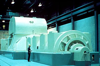
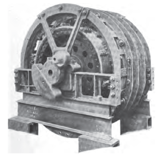
In electricity generation, a generator is a device that converts motion-based power or fuel-based power into electric power for use in an external circuit. Sources of mechanical energy include steam turbines, gas turbines, water turbines, internal combustion engines, wind turbines and even hand cranks. The first electromagnetic generator, the Faraday disk, was invented in 1831 by British scientist Michael Faraday. Generators provide nearly all the power for electrical grids.

A magnetometer is a device that measures magnetic field or magnetic dipole moment. Different types of magnetometers measure the direction, strength, or relative change of a magnetic field at a particular location. A compass is one such device, one that measures the direction of an ambient magnetic field, in this case, the Earth's magnetic field. Other magnetometers measure the magnetic dipole moment of a magnetic material such as a ferromagnet, for example by recording the effect of this magnetic dipole on the induced current in a coil.

A commutator is a rotary electrical switch in certain types of electric motors and electrical generators that periodically reverses the current direction between the rotor and the external circuit. It consists of a cylinder composed of multiple metal contact segments on the rotating armature of the machine. Two or more electrical contacts called "brushes" made of a soft conductive material like carbon press against the commutator, making sliding contact with successive segments of the commutator as it rotates. The windings on the armature are connected to the commutator segments.
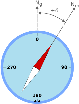
Magnetic declination is the angle between magnetic north and true north at a particular location on the Earth's surface. The angle can change over time due to polar wandering.
Magnetic deviation is the error induced in a compass by local magnetic fields, which must be allowed for, along with magnetic declination, if accurate bearings are to be calculated.

In electrical engineering, the armature is the winding of an electric machine which carries alternating current. The armature windings conduct AC even on DC machines, due to the commutator action or due to electronic commutation, as in brushless DC motors. The armature can be on either the rotor or the stator, depending on the type of electric machine.

The universal motor is a type of electric motor that can operate on either AC or DC power and uses an electromagnet as its stator to create its magnetic field. It is a commutated series-wound motor where the stator's field coils are connected in series with the rotor windings through a commutator. It is often referred to as an AC series motor. The universal motor is very similar to a DC series motor in construction, but is modified slightly to allow the motor to operate properly on AC power. This type of electric motor can operate well on AC because the current in both the field coils and the armature will alternate synchronously with the supply. Hence the resulting mechanical force will occur in a consistent direction of rotation, independent of the direction of applied voltage, but determined by the commutator and polarity of the field coils.
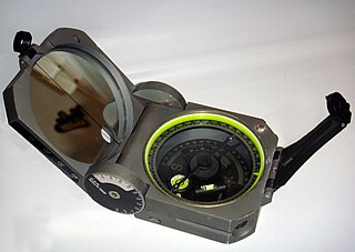
A Brunton compass, properly known as the Brunton Pocket Transit, is a precision compass made by Brunton, Inc. of Riverton, Wyoming. The instrument was patented in 1894 by Canadian-born geologist David W. Brunton. Unlike most modern compasses, the Brunton Pocket Transit utilizes magnetic induction damping rather than fluid to damp needle oscillation. Although Brunton, Inc. makes many other types of magnetic compasses, the Brunton Pocket Transit is a specialized instrument used widely by those needing to make accurate navigational and slope-angle measurements in the field. Users are primarily geologists, but archaeologists, environmental engineers, mining engineers and surveyors also make use of the Brunton's capabilities. The United States Army has adopted the Pocket Transit as the M2 Compass for use by crew-served artillery.
A repulsion motor is a type of electric motor which runs on alternating current (AC). It was formerly used as a traction motor for electric trains but has been superseded by other types of motors. Repulsion motors are classified as single phase motors.

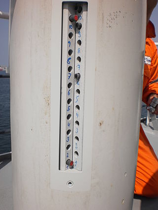
Diver navigation, termed "underwater navigation" by scuba divers, is a set of techniques—including observing natural features, the use of a compass, and surface observations—that divers use to navigate underwater. Free-divers do not spend enough time underwater for navigation to be important, and surface supplied divers are limited in the distance they can travel by the length of their umbilicals and are usually directed from the surface control point. On those occasions when they need to navigate they can use the same methods used by scuba divers.

Magnetic dip, dip angle, or magnetic inclination is the angle made with the horizontal by Earth's magnetic field lines. This angle varies at different points on Earth's surface. Positive values of inclination indicate that the magnetic field of Earth is pointing downward, into Earth, at the point of measurement, and negative values indicate that it is pointing upward. The dip angle is in principle the angle made by the needle of a vertically held compass, though in practice ordinary compass needles may be weighted against dip or may be unable to move freely in the correct plane. The value can be measured more reliably with a special instrument typically known as a dip circle.

The rotor is a moving component of an electromagnetic system in the electric motor, electric generator, or alternator. Its rotation is due to the interaction between the windings and magnetic fields which produces a torque around the rotor's axis.
A brushed DC electric motor is an internally commutated electric motor designed to be run from a direct current power source and utilizing an electric brush for contact.

A dynamo is an electrical generator that creates direct current using a commutator. Dynamos were the first electrical generators capable of delivering power for industry, and the foundation upon which many other later electric-power conversion devices were based, including the electric motor, the alternating-current alternator, and the rotary converter.
In electrical engineering, electric machine is a general term for machines using electromagnetic forces, such as electric motors, electric generators, and others. They are electromechanical energy converters: an electric motor converts electricity to mechanical power while an electric generator converts mechanical power to electricity. The moving parts in a machine can be rotating or linear. While transformers are occasionally called "static electric machines", since they do not have moving parts, generally they are not considered "machines", but as electrical devices "closely related" to the electrical machines.
Paul Renno Heyl was an American inventor, physicist, and author.
