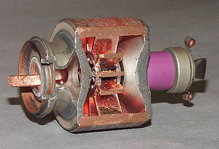
The tubes contain a single resonator.[5] The complete cavity is a rectangular box containing a ladder-like structure[6] through which the electron beam passes. Such a cavity has a large number of resonances but in the resonant mode used, large RF fields are developed in the gaps between the rungs. The phase advance from gap to gap is selected in such a way that an electron sees the same field at every gap, and it is described as being synchronous. In this context, the same field means a field of the same phase but not necessarily the same magnitude.
An electron beam which enters an RF excited cavity with approximately synchronous velocity will receive cumulative velocity modulation at each gap. After some distance into the resonator, repeatedly acceleratedelectrons will be catching up with electrons repeatedly decelerated, and bunches will form. These bunches will have a velocity close to the beam velocity. If the electron velocity is somewhat greater than synchronous, the bunches will start to cross gaps when the field is retarding, rather than zero. When this happens, the electrons are slowed; their lost energy is gained by the cavity and sustained oscillations become possible. As the velocity of the beam entering the cavity is increased further, more energy is transferred to the cavity and the frequency of oscillation rises somewhat. Eventually, however, the bunches punch through the retarding fields and oscillations cease abruptly. Reducing the beam velocity (voltage) will cause the tube to resume oscillation. However, it is necessary to reduce the beam velocity below the value at which oscillations ceased before oscillation will start again. This phenomenon is known as hysteresis and is similar to that observed in many reflex klystrons.
The frequency change which occurs as the beam voltage is raised is referred to as electronic tuning, and is typically 0.2% of the operating frequency measured from half power to cessation of oscillation. For larger frequency changes mechanical tuning is used which is obtained by moving one wall of the cavity. The moveable wall is, in fact, a piston which can be moved in a tunnel whose cross-section is that of the wall which it replaces. The range of mechanical tuning is usually limited by parasitic resonances which occur when the oscillating frequency and the frequency of one of the many other cavity resonances coincide. When this happens, serious loss is introduced, often enough to suppress oscillation completely. Typically, a mechanical tuning range of 4% can be obtained[7] but greater ranges have been demonstrated.
Apart from the resonant cavity, the Extended Interaction Oscillator is very similar to more conventional klystrons. An electron gun produces a narrow beam of electrons which is maintained at the required diameter by a magnetic field while it passes through the RF section. Thereafter, the beam enters a relatively field-free region where it spreads out and is collected by an appropriately cooled collector. Many of these oscillators have electrically isolated anodes and in these cases, the voltage between the cathode and anode determines the tube current which in turn determines the maximum power output.
↑ Roitman et al, High Power CW 264 GHz tunable Extended Interaction Oscillator, 14th International Vacuum Electronics Conference (IVEC), Paris, France 2013
Related Research Articles
An electronic oscillator is an electronic circuit that produces a periodic, oscillating or alternating current (AC) signal, usually a sine wave, square wave or a triangle wave, powered by a direct current (DC) source. Oscillators are found in many electronic devices, such as radio receivers, television sets, radio and television broadcast transmitters, computers, computer peripherals, cellphones, radar, and many other devices.
Microwave is a form of electromagnetic radiation with wavelengths shorter than other radio waves but longer than infrared waves. Its wavelength ranges from about one meter to one millimeter, corresponding to frequencies between 300 MHz and 300 GHz, broadly construed. A more common definition in radio-frequency engineering is the range between 1 and 100 GHz, or between 1 and 3000 GHz . The prefix micro- in microwave is not meant to suggest a wavelength in the micrometer range; rather, it indicates that microwaves are small, compared to the radio waves used in prior radio technology.
The cavity magnetron is a high-power vacuum tube used in early radar systems and subsequently in microwave ovens and in linear particle accelerators. A cavity magnetron generates microwaves using the interaction of a stream of electrons with a magnetic field, while moving past a series of cavity resonators, which are small, open cavities in a metal block. Electrons pass by the cavities and cause microwaves to oscillate within, similar to the functioning of a whistle producing a tone when excited by an air stream blown past its opening. The resonant frequency of the arrangement is determined by the cavities' physical dimensions. Unlike other vacuum tubes, such as a klystron or a traveling-wave tube (TWT), the magnetron cannot function as an amplifier for increasing the intensity of an applied microwave signal; the magnetron serves solely as an electronic oscillator generating a microwave signal from direct current electricity supplied to the vacuum tube.
A vacuum tube, electron tube, valve, or tube is a device that controls electric current flow in a high vacuum between electrodes to which an electric potential difference has been applied.
In electronics and telecommunications, a radio transmitter or just transmitter is an electronic device which produces radio waves with an antenna with the purpose of signal transmission up to a radio receiver. The transmitter itself generates a radio frequency alternating current, which is applied to the antenna. When excited by this alternating current, the antenna radiates radio waves.
A tetrode is a vacuum tube having four active electrodes. The four electrodes in order from the centre are: a thermionic cathode, first and second grids, and a plate. There are several varieties of tetrodes, the most common being the screen-grid tube and the beam tetrode. In screen-grid tubes and beam tetrodes, the first grid is the control grid and the second grid is the screen grid. In other tetrodes one of the grids is a control grid, while the other may have a variety of functions.
A klystron is a specialized linear-beam vacuum tube, invented in 1937 by American electrical engineers Russell and Sigurd Varian, which is used as an amplifier for high radio frequencies, from UHF up into the microwave range. Low-power klystrons are used as oscillators in terrestrial microwave relay communications links, while high-power klystrons are used as output tubes in UHF television transmitters, satellite communication, radar transmitters, and to generate the drive power for modern particle accelerators.
A linear particle accelerator is a type of particle accelerator that accelerates charged subatomic particles or ions to a high speed by subjecting them to a series of oscillating electric potentials along a linear beamline. The principles for such machines were proposed by Gustav Ising in 1924, while the first machine that worked was constructed by Rolf Widerøe in 1928 at the RWTH Aachen University. Linacs have many applications: they generate X-rays and high energy electrons for medicinal purposes in radiation therapy, serve as particle injectors for higher-energy accelerators, and are used directly to achieve the highest kinetic energy for light particles for particle physics.
A traveling-wave tube or traveling-wave tube amplifier is a specialized vacuum tube that is used in electronics to amplify radio frequency (RF) signals in the microwave range. It was invented by Andrei Haeff around 1933 as a graduate student at Caltech, and its present form was invented by Rudolf Kompfner in 1942–43. The TWT belongs to a category of "linear beam" tubes, such as the klystron, in which the radio wave is amplified by absorbing power from a beam of electrons as it passes down the tube. Although there are various types of TWT, two major categories are:
A resonator is a device or system that exhibits resonance or resonant behavior. That is, it naturally oscillates with greater amplitude at some frequencies, called resonant frequencies, than at other frequencies. The oscillations in a resonator can be either electromagnetic or mechanical. Resonators are used to either generate waves of specific frequencies or to select specific frequencies from a signal. Musical instruments use acoustic resonators that produce sound waves of specific tones. Another example is quartz crystals used in electronic devices such as radio transmitters and quartz watches to produce oscillations of very precise frequency.
The multipactor effect is a phenomenon in radio-frequency (RF) amplifier vacuum tubes and waveguides, where, under certain conditions, secondary electron emission in resonance with an alternating electromagnetic field leads to exponential electron multiplication, possibly damaging and even destroying the RF device.
A Gunn diode, also known as a transferred electron device (TED), is a form of diode, a two-terminal semiconductor electronic component, with negative differential resistance, used in high-frequency electronics. It is based on the "Gunn effect" discovered in 1962 by physicist J. B. Gunn. Its main uses are in electronic oscillators to generate microwaves, in applications such as radar speed guns, microwave relay data link transmitters, and automatic door openers.
A gyrotron is a class of high-power linear-beam vacuum tubes that generates millimeter-wave electromagnetic waves by the cyclotron resonance of electrons in a strong magnetic field. Output frequencies range from about 20 to 527 GHz, covering wavelengths from microwave to the edge of the terahertz gap. Typical output powers range from tens of kilowatts to 1–2 megawatts. Gyrotrons can be designed for pulsed or continuous operation. The gyrotron was invented by Soviet scientists at NIRFI, based in Nizhny Novgorod, Russia.
A crossed-field amplifier (CFA) is a specialized vacuum tube, first introduced in the mid-1950s and frequently used as a microwave amplifier in very-high-power transmitters.
A backward wave oscillator (BWO), also called carcinotron or backward wave tube, is a vacuum tube that is used to generate microwaves up to the terahertz range. Belonging to the traveling-wave tube family, it is an oscillator with a wide electronic tuning range.
The inductive output tube (IOT) or klystrode is a variety of linear-beam vacuum tube, similar to a klystron, used as a power amplifier for high frequency radio waves. It evolved in the 1980s to meet increasing efficiency requirements for high-power RF amplifiers in radio transmitters. The primary commercial use of IOTs is in UHF television transmitters, where they have mostly replaced klystrons because of their higher efficiencies and smaller size. IOTs are also used in particle accelerators. They are capable of producing power output up to about 30 kW continuous and 7 MW pulsed and power gains of 20–23 dB at frequencies up to about a gigahertz.
A microwave cavity or radio frequency cavity is a special type of resonator, consisting of a closed metal structure that confines electromagnetic fields in the microwave or RF region of the spectrum. The structure is either hollow or filled with dielectric material. The microwaves bounce back and forth between the walls of the cavity. At the cavity's resonant frequencies they reinforce to form standing waves in the cavity. Therefore, the cavity functions similarly to an organ pipe or sound box in a musical instrument, oscillating preferentially at a series of frequencies, its resonant frequencies. Thus it can act as a bandpass filter, allowing microwaves of a particular frequency to pass while blocking microwaves at nearby frequencies.
The Barkhausen–Kurz tube, also called the retarding-field tube, reflex triode, B–K oscillator, and Barkhausen oscillator was a high frequency vacuum tube electronic oscillator invented in 1920 by German physicists Heinrich Georg Barkhausen and Karl Kurz. It was the first oscillator that could produce radio power in the ultra-high frequency (UHF) portion of the radio spectrum, above 300 MHz. It was also the first oscillator to exploit electron transit time effects. It was used as a source of high frequency radio waves in research laboratories, and in a few UHF radio transmitters through World War 2. Its output power was low which limited its applications. However it inspired research that led to other more successful transit time tubes such as the klystron, which made the low power Barkhausen-Kurz tube obsolete.
Sutton tube was the name given to the first reflex klystron, developed in 1940 by Robert W. Sutton of Signal School group at the Bristol University. The Sutton tube was developed as a local oscillator for the receiver of 10cm microwave radar sets. Due to its geometry and long drift space, it suffered from mode jumping through the tuning range. For this reason, from late 1941 onward, it was replaced in many sets by the Western Electric 707A.
A twystron is a type of microwave-producing vacuum tube most commonly found in high-power radar systems. The name refers to its construction, which combines a traveling wave tube, or TWT, with a klystron, producing a tw-ystron. The name was originally a trademark of Varian Associates, its developer, and was often capitalized. In recent times has become a generic term for any similar design.
This page is based on this Wikipedia article Text is available under the CC BY-SA 4.0 license; additional terms may apply. Images, videos and audio are available under their respective licenses.