
Oliver Heaviside was an English mathematician and physicist who invented a new technique for solving differential equations, independently developed vector calculus, and rewrote Maxwell's equations in the form commonly used today. He significantly shaped the way Maxwell's equations are understood and applied in the decades following Maxwell's death. His formulation of the telegrapher's equations became commercially important during his own lifetime, after their significance went unremarked for a long while, as few others were versed at the time in his novel methodology. Although at odds with the scientific establishment for most of his life, Heaviside changed the face of telecommunications, mathematics, and science.

William Thomson, 1st Baron Kelvin, was a British mathematician, mathematical physicist and engineer. Born in Belfast, he was the professor of Natural Philosophy at the University of Glasgow for 53 years, where he undertook significant research and mathematical analysis of electricity, was instrumental in the formulation of the first and second laws of thermodynamics, and contributed significantly to unifying physics, which was then in its infancy of development as an emerging academic discipline. He received the Royal Society's Copley Medal in 1883 and served as its president from 1890 to 1895. In 1892, he became the first scientist to be elevated to the House of Lords.

Electric power transmission is the bulk movement of electrical energy from a generating site, such as a power plant, to an electrical substation. The interconnected lines that facilitate this movement form a transmission network. This is distinct from the local wiring between high-voltage substations and customers, which is typically referred to as electric power distribution. The combined transmission and distribution network is part of electricity delivery, known as the electrical grid.
In electrical engineering, electrical length is a dimensionless parameter equal to the physical length of an electrical conductor such as a cable or wire, divided by the wavelength of alternating current at a given frequency traveling through the conductor. In other words, it is the length of the conductor measured in wavelengths. It can alternately be expressed as an angle, in radians or degrees, equal to the phase shift the alternating current experiences traveling through the conductor.

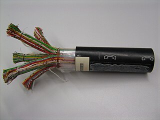
A loading coil or load coil is an inductor that is inserted into an electronic circuit to increase its inductance. The term originated in the 19th century for inductors used to prevent signal distortion in long-distance telegraph transmission cables. The term is also used for inductors in radio antennas, or between the antenna and its feedline, to make an electrically short antenna resonant at its operating frequency.

In radio engineering and telecommunications, standing wave ratio (SWR) is a measure of impedance matching of loads to the characteristic impedance of a transmission line or waveguide. Impedance mismatches result in standing waves along the transmission line, and SWR is defined as the ratio of the partial standing wave's amplitude at an antinode (maximum) to the amplitude at a node (minimum) along the line.

In electrical engineering, a transmission line is a specialized cable or other structure designed to conduct electromagnetic waves in a contained manner. The term applies when the conductors are long enough that the wave nature of the transmission must be taken into account. This applies especially to radio-frequency engineering because the short wavelengths mean that wave phenomena arise over very short distances. However, the theory of transmission lines was historically developed to explain phenomena on very long telegraph lines, especially submarine telegraph cables.

Alternating current (AC) is an electric current that periodically reverses direction and changes its magnitude continuously with time, in contrast to direct current (DC), which flows only in one direction. Alternating current is the form in which electric power is delivered to businesses and residences, and it is the form of electrical energy that consumers typically use when they plug kitchen appliances, televisions, fans and electric lamps into a wall socket. The abbreviations AC and DC are often used to mean simply alternating and direct, respectively, as when they modify current or voltage.

Coaxial cable, or coax, is a type of electrical cable consisting of an inner conductor surrounded by a concentric conducting shield, with the two separated by a dielectric ; many coaxial cables also have a protective outer sheath or jacket. The term coaxial refers to the inner conductor and the outer shield sharing a geometric axis.
In physics, the Poynting vector represents the directional energy flux or power flow of an electromagnetic field. The SI unit of the Poynting vector is the watt per square metre (W/m2); kg/s3 in base SI units. It is named after its discoverer John Henry Poynting who first derived it in 1884. Nikolay Umov is also credited with formulating the concept. Oliver Heaviside also discovered it independently in the more general form that recognises the freedom of adding the curl of an arbitrary vector field to the definition. The Poynting vector is used throughout electromagnetics in conjunction with Poynting's theorem, the continuity equation expressing conservation of electromagnetic energy, to calculate the power flow in electromagnetic fields.
In information theory, the Shannon–Hartley theorem tells the maximum rate at which information can be transmitted over a communications channel of a specified bandwidth in the presence of noise. It is an application of the noisy-channel coding theorem to the archetypal case of a continuous-time analog communications channel subject to Gaussian noise. The theorem establishes Shannon's channel capacity for such a communication link, a bound on the maximum amount of error-free information per time unit that can be transmitted with a specified bandwidth in the presence of the noise interference, assuming that the signal power is bounded, and that the Gaussian noise process is characterized by a known power or power spectral density. The law is named after Claude Shannon and Ralph Hartley.
In electrical circuits, reactance is the opposition presented to alternating current by inductance and capacitance. Along with resistance, it is one of two elements of impedance; however, while both elements involve transfer of electrical energy, no dissipation of electrical energy as heat occurs in reactance; instead, the reactance stores energy until a quarter-cycle later when the energy is returned to the circuit. Greater reactance gives smaller current for the same applied voltage.

Transatlantic telegraph cables were undersea cables running under the Atlantic Ocean for telegraph communications. Telegraphy is an obsolete form of communication, and the cables have long since been decommissioned, but telephone and data are still carried on other transatlantic telecommunications cables.

In electrical engineering, impedance matching is the practice of designing or adjusting the input impedance or output impedance of an electrical device for a desired value. Often, the desired value is selected to maximize power transfer or minimize signal reflection. For example, impedance matching typically is used to improve power transfer from a radio transmitter via the interconnecting transmission line to the antenna. Signals on a transmission line will be transmitted without reflections if the transmission line is terminated with a matching impedance.

The RC time constant, denoted τ, the time constant of a resistor–capacitor circuit, is equal to the product of the circuit resistance and the circuit capacitance :
A transmission line which meets the Heaviside condition, named for Oliver Heaviside (1850–1925), and certain other conditions can transmit signals without dispersion and without distortion. The importance of the Heaviside condition is that it showed the possibility of dispersionless transmission of telegraph signals.In some cases, the performance of a transmission line can be improved by adding inductive loading to the cable.
Ripple in electronics is the residual periodic variation of the DC voltage within a power supply which has been derived from an alternating current (AC) source. This ripple is due to incomplete suppression of the alternating waveform after rectification. Ripple voltage originates as the output of a rectifier or from generation and commutation of DC power.
The telegrapher's equations are a set of two coupled, linear equations that predict the voltage and current distributions on a linear electrical transmission line. The equations are important because they allow transmission lines to be analyzed using circuit theory. The equations and their solutions are applicable from 0 Hz to frequencies at which the transmission line structure can support higher order non-TEM modes. The equations can be expressed in both the time domain and the frequency domain. In the time domain the independent variables are distance and time. The resulting time domain equations are partial differential equations of both time and distance. In the frequency domain the independent variables are distance and either frequency, , or complex frequency, . The frequency domain variables can be taken as the Laplace transform or Fourier transform of the time domain variables or they can be taken to be phasors. The resulting frequency domain equations are ordinary differential equations of distance. An advantage of the frequency domain approach is that differential operators in the time domain become algebraic operations in frequency domain.
Analogue filters are a basic building block of signal processing much used in electronics. Amongst their many applications are the separation of an audio signal before application to bass, mid-range, and tweeter loudspeakers; the combining and later separation of multiple telephone conversations onto a single channel; the selection of a chosen radio station in a radio receiver and rejection of others.
The primary line constants are parameters that describe the characteristics of conductive transmission lines, such as pairs of copper wires, in terms of the physical electrical properties of the line. The primary line constants are only relevant to transmission lines and are to be contrasted with the secondary line constants, which can be derived from them, and are more generally applicable. The secondary line constants can be used, for instance, to compare the characteristics of a waveguide to a copper line, whereas the primary constants have no meaning for a waveguide.


