* A debug monitor and simple operating system (OS) was included with the devices. CP/M versions 1.4, 2.2 and 3.0 were also available later.
History
The history of Nascom starts with the history of John A. Marshall. Marshall was the "& Son" of "A Marshall & Son (London) Ltd",[2] an electronic component retailer whose adverts were a regular feature in hobby electronics magazines from as early as 1967.[3]
Marshall was a director of a company called Nasco Sales Ltd; a UK distributor of US semiconductors. He was also connected with a company called Lynx Electronics (London) Ltd. which had been a regular advertiser in the hobby electronics press since 1976.[4]
During a business trip to California in the Autumn of 1976, Marshall attended an amateur computer club meeting at Stanford University. On the flight home, he started to wonder whether there was a market in the UK for a kit computer. Marshall used the price of an SLR camera (about £200) as a reference point for the amount someone might be prepared to spend on a "hobby" purchase.[2]
At the end of 1976, Marshall attended a microprocessor seminar at Imperial College and met Phil Pitman. Pitman was the marketing manager for Mostek, which had recently become a second source for Zilog's Z80 processor.[2] Pitman put Marshall in touch with a design consultant named Chris Shelton and, in the spring of 1977, Marshall commissioned Shelton Instruments to design the Nascom 1.[1]
Most of the details of the Nascom design were described in a series of articles by Pitman that appeared in Wireless World between November 1977 and January 1979.[5]
By July 1977, monthly magazine adverts by Lynx Electronics were starting to hint about a microprocessor seminar in the autumn and a forthcoming computer product.[6]
On Saturday, 26 November 1977, Lynx Electronics launched the Nascom 1 at their "Home Microcomputer Symposium" at Wembley Conference Centre, London.[7] Tickets cost £3.50 and hosting the event on a Saturday pitched it at an amateur/hobbyist rather than a professional audience. The event included a raffle for a Nascom 1 computer kit. About 550 people attended the symposium and over 300 kits were sold in the two weeks following the launch.[8]
The symposium was covered in detail in Issue 1 of PCW magazine and the Nascom 1 was the cover photograph for that issue (though not with the final keyboard). An article in that issue[9] by K. S. Borland (another director of Nasco Sales Ltd) described the origins and history of the Nascom 1 design.
In January 1978, the Lynx Electronics advert in Practical Electronics listed the Nascom 1 in addition to their traditional list of electronic components. By February 1978 and thereafter the whole of their advert was devoted to the Nascom 1.[10]
After the success of their seminar in Wembley, Lynx electronics held a similar event in Manchester (Saturday, 1 April 1978. Tickets cost £5.50).[11]
The launch price for the Nascom 1 was £197.50 plus 8% VAT,[10] in kit form. The kit included keyboard and sockets for some (but not all) of the ICs. The purchaser needed to supply a TV, a cassette recorder and a power supply. Over its lifetime, the price was reduced to £165 + VAT (March 1979) then £125 + VAT or £140 + VAT assembled (January 1980).
By July 1978, The Micronics Company was advertising a cased, built and tested Nascom 1 (with power supply) for £399 + VAT.[12] The advert does not name the machine as a Nascom 1 but the specification is identical.
By January 1979, Lynx Electronics had appointed multiple dealers in the UK and were advertising as Nascom Microcomputers, with the "nm" logo.[13]
In September 1979, PCW reported that Grovewood Securities had invested £500,000 in Nascom.[14] The same article reported that PAL full-colour support would arrive for the Nascom by "the new year".
In September 1979, the Nascom 2 (kit) was announced with a list price of £295 + VAT.[15]
Then, Nascom were hit by a shortage of Mostek MK4118 1Kx8 RAM devices. 10 devices were required per Nascom 2 (1 each for video RAM and workspace RAM respectively, 8 for user RAM) but Nascom were only able to source 5,000 parts.[16] By November 1979 Nascom had decided to relaunch the product with a 16Kbyte DRAM board and NASBUS interconnect but to keep the price at £295 + VAT.[17] This arrangement only required 2 MK4118 devices, allowing Nascom to ship 2,500 systems. By December 1979, PCW reported that the first deliveries of the Nascom 2 were going out.[16]
On 23 May 1980, Nascom reported[18] that it had asked Grovewood Securities Ltd to appoint a receiver after it had been unable to secure further investment. Grovewood appointed Messrs Cork Gully, and Marshall resigned from the company to start a new business, Gemini Computers.[2]
Nascom continued to trade in receivership. In July 1981, PCW reported[19] that Nascom had been bought by Lucas Industries; the same issue contained a full-page advert under the name "Nascom Microcomputers. Division of Lucas Logic Ltd".[20]
In December 1981, the Nascom 3 was launched.[21] This was basically a cased Nascom 2 with some expansion boards.
In June 1984, the final issue of the Nascom Newsletter was published.[22]
In January 1985, PCW published a letter from Lucas Nascom stating that, while the Nascom 1 had been discontinued, the Nascom 2 and Nascom 3 were still in production.[23]
Unit Sales
A Nascom advert in January 1980[24] claimed "over 15,000 systems in operation world-wide".
In a retrospective published in May 1989,[2] Marshall claimed that, by May 1980, Nascom had shipped over 35,000 Nascom 1 and Nascom 2 systems, all in kit form.
Nascom reported sales of £250,000 in April 1980[25]
Documentation
The Nascom 1 and Nascom 2 were supplied with full documentation including circuit schematics, construction guide, datasheets for some components and assembly listing for the ROM monitor. An annotated disassembly listing of the Nascom 2 Microsoft ROM BASIC was published[26] and the code was subsequently re-purposed in retrocomputing projects such as Grant Searle's Multicomp and Spencer Owen's RC2014. The source code can now be found on GitHub.[27]
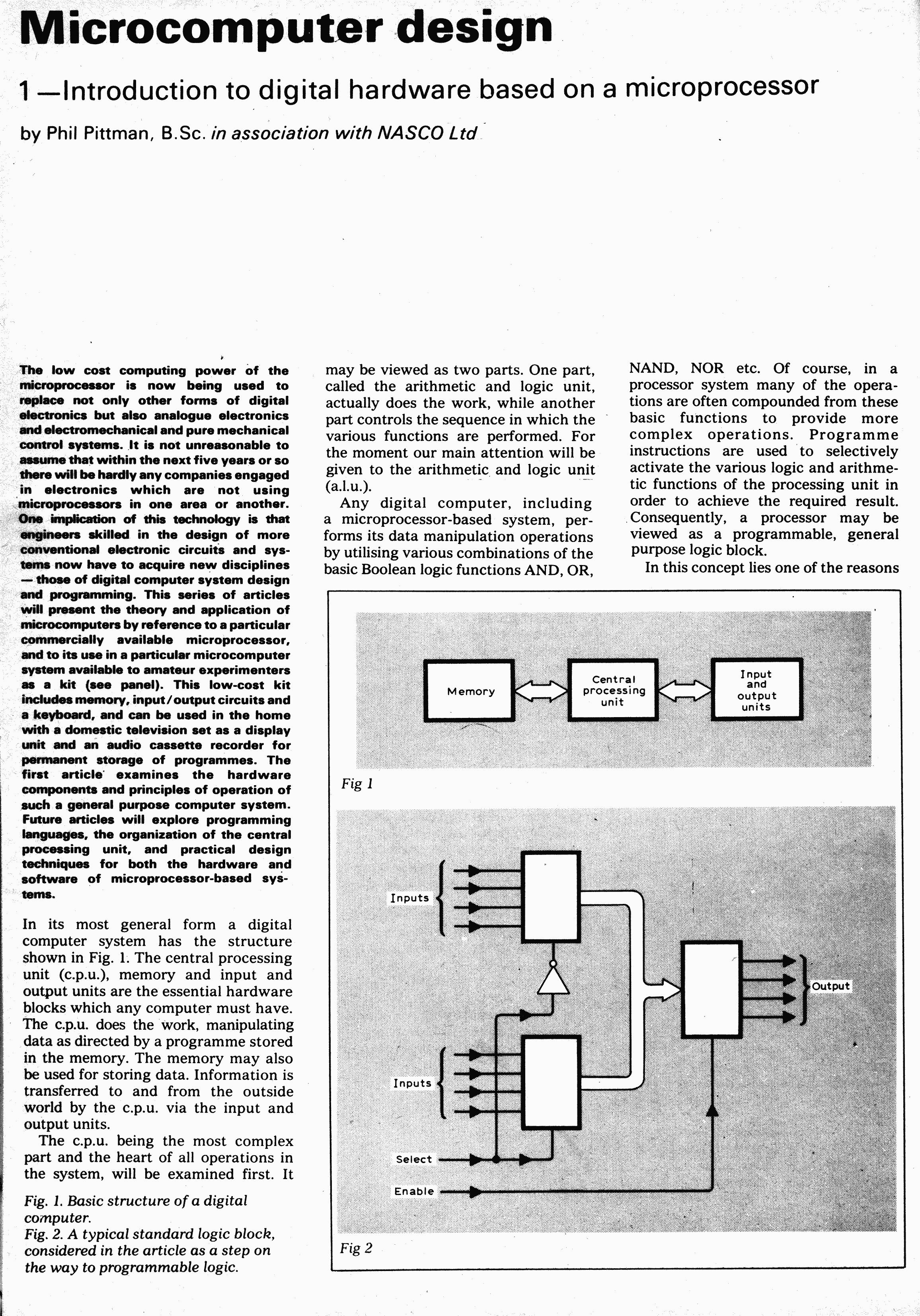
Hardware
Assembled Nascom 1 computer
The Nascom 1[28] and Nascom 2[29] hardware designs had these features in common:
A 16MHz crystal biased into oscillation and then divided down to create the clocks for the CPU, the serial communications and the video interface
A Harris 6402 UART (or equivalent) that could be used either to communicate with a serial device (e.g. RS232 terminal or printer) or to save and load data using a domestic compact cassette recorder.
A memory-mapped video display and a UHF video modulator capable of driving a domestic TV
Circuitry decoded on IO port 0 to control a software-scanned keyboard, to drive a LED ("DRIVE") and to generate a timed non-maskable interrupt (NMI) that was used to provide a hardware single-step capability
An LED ("HALT") on the Z80-CPU "/HALT" output, to provide a visual indication that the CPU was halted.
The I/O address map was common between the Nascom 1 and Nascom 2 designs, and the memory address map of the Nascom 2 was a superset of the Nascom 1 memory address map; this allowed a high degree of software compatibility between the two machines.
The Nascom 1 was implemented entirely using off-the-shelf integrated-circuits and other electronic components. The Nascom 2 used 4, 16-pin bipolarPROMs which acted as glue logic for decode functions ("N2MD" for memory decode, "N2IO" for I/O decode, "N2V" for video decode and N2DB" for data bus buffer control).
The Nascom 2 had these additional features that were not present on the Nascom 1:
Power-on reset with timing control to reset the CPU without interrupting the periodic refresh cycles produced by the Z80
Gating to reset the Z80-PIO (the Z80-PIO has no dedicated reset input)
A reset-jump circuit that allowed the Z80-CPU to start execution from any 4-Kbyte boundary after reset (the Z80-CPU usually fetches from address 0 after reset). This allowed, for example, control to be passed straight to the BASIC interpreter after reset.
Microsoft BASIC in an 8Kbyte ROM.
Two groups of 4 uncommitted 24-pin DIL sockets. Each group could be configured to accommodate 1Kx8 ROM or RAM devices and decoded at a start address of 0x1000, 0x2000, 0xB000, 0xC000 or 0xD000.
Full buffering of the CPU address, data and control to generate the "NAS-BUS" expansion bus.
The Nascom 1 used DIL sockets for making external connections. The photo shows 4 sockets, used for keyboard, serial (cassette and/or teletype/printer), PIO port A, PIO port B. The small "daughterboard" is a home-made implementation of the "snow plough" circuit referred to below.
The I/O address map was decoded as follows:
I/O Port address
Function
0x0 (read)
Read keyboard state
0x0 (write)
Control keyboard, control single-step (NMI) logic, control "DRIVE" LED
0x1
UART Data
0x2
UART Control/Status
0x3
Unused
0x4
Z80-PIO Data Port A
0x5
Z80-PIO Data Port B
0x6
Z80-PIO Control Port A
0x7
Z80-PIO Control Port B
On an unexpanded system, these 8 ports were repeated through the whole of the I/O address space. On an expanded system, the bus signal /NASIO allowed control of the I/O address space.
The memory address map was decoded as follows:
Address
Nascom 1
Nascom 2
0x0000-0x07FF
Monitor (NASBUG, T4, NAS-SYS1, NAS-SYS3)
1 or 2 1Kbyte 2708 EPROM
Monitor (NAS-SYS1 or NAS-SYS3)
2Kbyte ROM or 2716 EPROM
0x0800-0x0BFF
Video RAM
Video RAM
0x0C00-0x0FFF
Workspace RAM
Workspace RAM
0x1000-0x1FFF
Decoded on board. Usually used for RAM (4, 1Kbyte devices)
0x2000-0x2FFF
Decoded on board. Usually used for RAM (4, 1Kbyte devices)
0xB000-0xBFFF
Decoded on board. Usually used for EPROM (4, 1Kbyte 2708 devices)
0xC000-0xCFFF
Decoded on board. Usually used for EPROM (4, 1Kbyte 2708 devices)
0xD000-0xDFFF
Decoded on board. Usually used for EPROM (4, 1Kbyte 2708 devices)
0xE000-0xFFFF
Microsoft 8Kbyte ROM BASIC
Keyboard
Nascom 2 (top) and Nascom 1 (bottom) keyboardsNascom 2 (top) had angled key-tops and Nascom 1 (bottom) did not
The Nascom keyboards used Licon solid-state (induction transformer) key switches in a matrix arrangement which was scanned under software control. The keys were mounted in a metal frame that was riveted to a single-sided fibreglassPCB. The frame improves reliability by preventing the force of repeated keystrokes from being transmitted to the solder joints that connect the key switches to the PCB. A separate, conventional, key switch was provided on the keyboard for hardware reset.
The Nascom 1 had 47 keys. The Nascom 2 had 10 additional keys (GRAPH, which toggled bit 7, CTRL, a second SHIFT key, 4 cursor direction keys, LF/CH and keys for [ and ]).
The Nascom 2 keyboard was designed to be mounted at an angle; it had angled key-caps which were horizontal when the keyboard itself was mounted at an angle. The key-caps on the Nascom 1 were not angled (see photo).
The keyboard was always supplied assembled, even when the rest of the Nascom was supplied as a kit.
The Nascom 1 used a 16-pin IC-style DIL socket at each end of the connection from the keyboard to the computer main board. The Nascom 2 used a 0.1" 2x8 male header (16 pins total) at each end. In each case, the connectors use the same physical ordering of signals but the pin numbers do not correspond (because DIL sockets and IDC headers use different numbering conventions). The Nascom 2 keyboard has an additional "sense" output.
Both Nascom 1 and Nascom 2 main boards had connections to the keyboard connectors that were unused on the keyboard. On the Nascom 2, this included a connection to the /NMI (non-maskable interrupt) signal.
Video Display
Nascom character set, characters 0–127, displayed on a Nascom 2 and photographed on a monochrome non-interlaced CRT monitorCharacter cell on Nascom 2: 8 pixels by 14 rows. Photographed on a monochrome non-interlaced CRT monitor
The display of the Nascom 1 and 2 was memory-mapped and consisted of 16 rows of 48 characters. Each row of characters used 64 consecutive memory locations; the extra 16 characters in each line were "hidden" by the video blanking circuitry.
Scrolling was implemented under software control. Due to an idiosyncrasy of the video memory decoding on the Nascom 1 (which was then retained on the Nascom 2), the lines were decoded discontiguously, with the top line of the display being the 16th region of memory. The top line was not scrolled, except by the Nascom CP/M implementation.
The Nascom 1 used a MCM6576P character generator to display 128 characters (bit 7 of the memory was ignored). The Nascom 2 used an identical character set but implemented it in a ROM that was footprint compatible with a 2716 2Kbyte device. The Nascom 2 allowed a second 2Kbyte character generator ROM (or EPROM) to be fitted (approximate price £20 in 1980) . The so-called NAS-GRA ROM was used to display characters with the byte codes 0x80–0xFF. The built-in Microsoft BASIC (8K ROM) interpreter could use these graphics to create a crude, blocky 96×48 graphics display.
Each character was 8 pixels wide and 16 pixels high, allowing display of true descenders. Therefore, a character occupied 16 bytes in the ROM (so that 256 characters required a total of 256*16=4Kbytes of character generator storage). Characters were abutted vertically and horizontally on the display and so the design of the characters within the character generator included vertical and horizontal inter-character spacing. On the Nascom 1, all 16 rows of the character were displayed, so that the whole image occupied 16*16=256 rows. On the Nascom 2, the top 12 or 14 rows of the character were displayed (controlled by the setting of a switch/jumper on the main board). The 12-row setting was intended for 525 line displays in 60Hz geographies and the 14-row setting was intended for 625-line displays in 50Hz geographies.
The design of the video display required that the CPU and the video circuitry shared access to the video RAM (the CPU had read/write access and the video circuitry had read-only access). If the CPU and the video circuitry accesses the video RAM simultaneously, the CPU was given priority and the video circuitry would read incorrect data. On the Nascom 1 this gave rise to white flicker on the screen that was termed "snow". The International Nascom Microcomputer Club (INMC) published a "snow plough" design that reduced the effect by blanking the video when simultaneous access occurred.[30] The Nascom 2 used a slightly different design but still allowed contention to occur, this time giving rise to black flicker (blanking) on the screen.
Software
Mask-programmed 2Kx8 ROMs containing the NAS-SYS 1 debug monitor
Initially, users were expected to write their own software. On the earliest machines with limited memory this meant writing Z80 assembly language on paper, assembling it by hand and then using the monitor program to enter it in hexadecimal format.
The Nascom 1 provided two 24-pin 0.6"-pitch DIL sockets for ROM memory, each wired to accept a 2708 1 KB device. The first monitor program on the Nascom 1 was named NAS-BUG and was supplied as a single 1 KB 2708 EPROM. This was superseded by NAS-BUG T2. All later versions of the monitor were 2 KB in size and so occupied both ROM sockets. The 2 KB monitors were BBUG (a 1 KB extension that co-existed with T2), T4, NAS-SYS 1 and NAS-SYS 3.
The Nascom 2 provided one 24-pin 0.6"-pitch DIL socket for ROM memory (other sockets on the Nascom 2 board could also be configured to accommodate ROMs), wired to accept a 5V 2716 2 KB device. Nascom 2 kits were initially provided with NAS-SYS 1 in masked ROM (the photo shows that at least two date-codes exist for these ROMs). NAS-SYS 1 was the only Nascom monitor ROM to be supplied as masked ROM; all other versions were supplied as EPROMs.
All of the debug monitors provided similar capabilities, with different levels of sophistication:
Examine and modify memory
Start program execution from a specified address
Insert a breakpoint (in RAM only)
Single-step (through ROM or RAM) and display registers. Hardware support was provided for this, using the Z80 non-maskable interrupt
Save a memory region to/load a memory region from cassette tape
Later, commercial software was made available either on cassette tape or programmed into one or more EPROMs (usually 1 KB 2708 devices).
When disk drives became available, various disk operating systems became available, including PolyDos (developed by Anders Hejlsberg and inspired by the software of the PolyMorphic SystemsPoly-88), NAS-DOS and CP/M.
The predecessor of Borland's very successful Turbo Pascalcompiler and integrated development environment (IDE) for CP/M and DOS was developed by Anders Hejlsberg of Blue Label Software for the Nascom 2, under the name Blue Label Software Pascal, or BLS Pascal.
In 1979 the Nascom 2 came with an onboard ROM with early Microsoft Basic 8 KB interpreter.
Nascom defined an expansion bus, named NAS-BUS, allowing many other cards to be added to the Nascom. The Nascom 1 required a buffer board to generate the NAS-BUS; the buffer board was connected to a 43-way (42-way plus polarising slot) 0.1" pitch tinned edge connector on its PCB. The Nascom 2 generated the NAS-BUS directly on an 80-way (79-way plus polarising slot) 0.1" pitch gold-plated edge connector on its PCB.
NAS-BUS was initially proprietary but quickly superseded by the 80-bus. The standard size for these cards was 8"x8" in order to fit in a "standard" 8" rack. However, some boards were produced in other sizes. Other manufacturers (including Gemini and MAP80 Systems) produced their own 80-bus CPU boards, which allowed an entire non-Nascom system to be built. Gemini 80-bus systems were, for a while, used as an industrial process controller. British Cellophane used several to continuously monitor thickness gauges attached to plastic sheet production lines. An 80-bus compatible network card enabled both Nascom and Gemini computers to be used in office environments.
Miscellaneous
In the early 1980s, one of the first generation of computer retailers, Kenilworth Computers, released a version of the Nascom microcomputer with the selling point that it was robust enough to be used by agriculture.
Movement Computer Systems used the Nascom 2 as the controller for their MCDU1 and MCDU2 drum machines.[34][35]
12345Marshall, John (May 1989). "From The Horse's Mouth"(PDF). Scorpio News: 25. Archived(PDF) from the original on 2018-05-24. Retrieved 21 May 2022.
↑A Marshall & Son (November 1967). "Advert"(PDF). Practical Electronics: 858. Archived(PDF) from the original on 2020-08-31. Retrieved 21 May 2022.
↑Lynx Electronics (London) Ltd (August 1976). "Advert"(PDF). Practical Electronics: 668. Archived(PDF) from the original on 2020-08-24. Retrieved 21 May 2022.
↑Lynx Electronics (London) Ltd (July 1977). "Watch This Space"(PDF). Practical Electronics. Archived(PDF) from the original on 2020-08-31. Retrieved 21 May 2022.
↑Lynx Electronics (London) Ltd (November 1977). "The Home Computer Forum"(PDF). Practical Electronics: 212. Archived(PDF) from the original on 2020-08-24.
↑"News Briefs"(PDF). Practical Electronics: 417. Retrieved 21 May 2022.
↑Borland, Kerr. "Yours To Command"(PDF). Personal Computer World (1): 20. Archived(PDF) from the original on 2020-07-08. Retrieved 21 May 2022.
↑Lynx Electronics (London) Ltd (April 1978). "Advert: Manchester seminar"(PDF). Practical Electronics: 614. Archived(PDF) from the original on 2020-08-31. Retrieved 21 May 2022.
↑The Micronics Company (July 1978). "Advert"(PDF). Personal Computer World: 45. Archived(PDF) from the original on 2020-07-08. Retrieved 21 May 2022.
↑Nascom Microcomputers (January 1979). "Advert"(PDF). Electronics Today International: 46. Archived(PDF) from the original on 2020-07-08. Retrieved 21 May 2022.
↑Kewney, Guy (September 1979). "Newsprint"(PDF). Personal Computer World: 30. Archived(PDF) from the original on 2020-07-08. Retrieved 22 May 2022.
↑Turpin, Alan; Shortland, David (September 1979). "Market Place"(PDF). Practical Electronics: 27. Archived(PDF) from the original on 2020-08-31. Retrieved 22 May 2022.
12Kewney, Guy (December 1979). "Newsprint"(PDF). Personal Computer Work. p.32. Archived(PDF) from the original on 2020-07-08. Retrieved 22 May 2022.
↑Nascom Microcomputers (November 1979). "Advert"(PDF). Personal Computer World: 21. Archived(PDF) from the original on 2020-07-08.
↑Nascom Computers (July 1981). "Advert"(PDF). Personal Computer World: 52. Retrieved 22 May 2022.
↑Nascom Microcomputers (December 1981). "Advert"(PDF). Personal Computer World: 100. Archived(PDF) from the original on 2021-03-08. Retrieved 22 May 2022.
↑Clemmett, Ian J. (June 1984). "Editorial"(PDF). Nascom Newsletter. p.2. Archived(PDF) from the original on 2018-05-24.
↑Seddon, Peter (January 1985). "The Nascom Lives!"(PDF). Personal Computer World: 131. Archived(PDF) from the original on 2022-05-22. Retrieved 22 May 2022.
↑"Advert"(PDF). Personal Computer World: 17. January 1980. Archived(PDF) from the original on 2020-07-08. Retrieved 21 May 2022.
↑"The Nascom Home Page". nascomhomepage.com. 2022-05-30. Retrieved November 1, 2025. Comprehensive archive of NASCOM software, emulators, manuals, and games including Adventure 16K/32K (Syrtis Soft.), Level 9 Computing titles, Program Power games, and INMC Soft. Library programs.
↑Hans Persson (creator); Stefan Meier (maintainer). "Adventureland: NASCOM". Adventureland. Lysator Academic Computer Society. Retrieved November 1, 2025. Database listing 7 text adventure games for NASCOM, including Colossal Adventure, Adventure Quest, Dungeon Adventure, Snowball, and Lords of Time by Level 9 Computing.{{cite web}}: CS1 maint: multiple names: authors list (link)
This page is based on this Wikipedia article Text is available under the CC BY-SA 4.0 license; additional terms may apply. Images, videos and audio are available under their respective licenses.


